
The Wire Harness Assembly Process: 7 Steps Explained
- Key Takeaways
- What Are the Steps in the Wire Harness Assembly Process?
- How Are Wire Harnesses Tested?
- Is Wire Harness Assembly Manual or Automated?
- What IPC/WHMA-A-620 Requires, and Why You Should Specify a Class
- Design Choices That Cut Harness Cost Before Assembly Starts
- FAQ
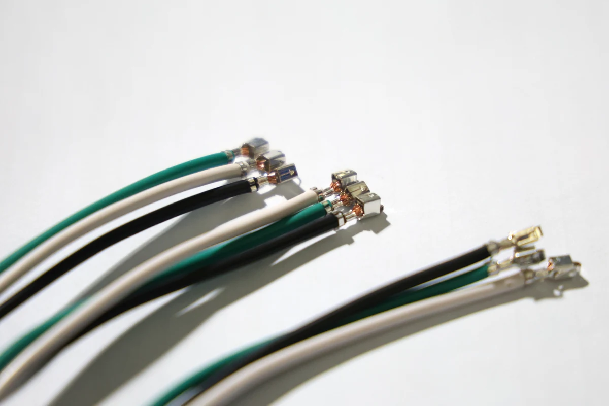
Wire harness assembly is the process of joining wires, terminals, connectors, and protective coverings to build a single component. That component can then be installed into a product in a single step, rather than installing each individual part. The unit can also be tested before it ships out to the manufacturer,
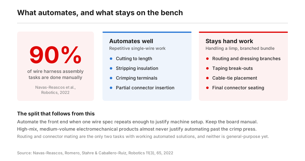
Wire harness assembly refers specifically to a build sequence, not the part that it produces. The wires are cut and stripped, the terminals are crimped, the connectors are populated, the bundle is laid out and secured on a form board, and then the finished harness is electrically tested. Unlike many other manufacturing processes, these tasks are mostly still done by hand. According to a 2022 review in Robotics, 90% of wire harness assembly tasks are performed manually. And out of these tasks, only cable routing and connector mating have working automated solutions at all.
Because automation is so difficult, the quality of a harness depends on operator technique at a dozen separate points. This is also where defects usually hide until final functional test or, worse, once the product is already in the field.
Key Takeaways
Wire harnesses are sub-assemblies that consist of wires, terminals, connectors, and protective coverings.
Assembling wire harnesses consists of several steps, including cutting and stripping wires, crimping connectors, and electrical testing.
The first steps in the assembly process (cutting, stripping, crimping) can be automated, but much of the form board work needs to be done manually.
Wire harnesses are tested against the IPC/WHMA-A-620 standard, with different requirements for Class 1, 2, or 3 assemblies.
Table of Contents
What Are the Steps in the Wire Harness Assembly Process?
There are seven steps, in this order:
- Cut and strip the wires to the lengths on the wire list.
- Crimp terminals or contacts onto the conductors.
- Populate the connectors by inserting contacts into the correct cavities.
- Lay out and route the bundle on a form board.
- Apply protective coverings such as tape, sleeve, conduit, and heat shrink.
- Electrically test every net on the finished harness.
- Inspect, label, and pack the harness against the specified acceptance class.
Each stage has a characteristic way of going wrong, and it’s worth knowing about these potential issues before buying a harness or specifying one.
Step 1. Cut and Strip
First, wires are cut to the lengths on the wire list and the insulation is removed at both ends. How carefully or skillfully the insulation is stripped can affect the quality of the assembly, since a nicked strand could become a stress point that survives testing but fails after a few thousand vibration cycles.
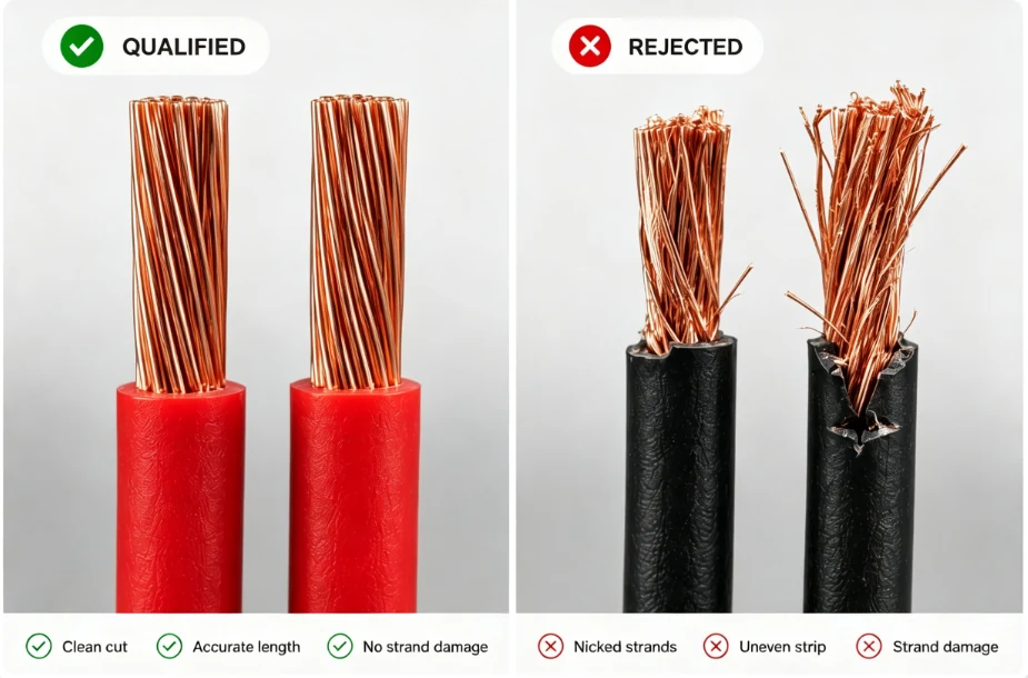
Common problems at this step: nicked or severed conductor strands, strip length out of spec, the wrong gauge has been pulled from the rack.
Step 2. Crimp
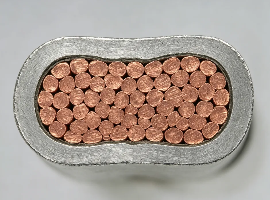
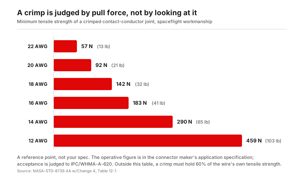
For any combination that is not covered by that table, the standard requires the crimp to hold at least 60% of the tensile strength of the wire itself. But remember to treat these as ballpark values. Ultimately, your commercial harness will need to be built according to the connector maker’s crimp spec and inspected in conformity with the IPC/WHMA-A-620 standard.
Verification is also important at this stage. The standard requires crimp tools and each tool-contact-conductor combination to be tested “at the start and at the end of each work shift or production run, whichever is shorter.” Production may not proceed until there are zero failures out of three samples. So when evaluating suppliers, be specific about pull testing and ask how often they do it, on what sample size, and what happens to the parts that were built since the last test. If a manufacturer only tests their production line at the start of the shift, they won’t notice if the quality starts to drift throughout the workday.
Common problems at this step: under-crimping, which causes the part to fail the pull test; over-crimping, which cuts strands; insulation trapped in the wire barrel.
Step 3. Populate the Connectors
The contacts then go into connector housings according to the pinout. When assembling a 40-way connector, that means there are 40 chances to put a contact in the wrong cavity. And these errors are no longer visible once the housing is closed.
Another potential defect happens when a contact isn’t fully seated. When this happens, the part might still pass a bench continuity check, but then fail under vibration or when someone tugs the leg during installation. Operators can confirm that connectors have been securely installed by feel and by giving a gentle pull on each wire after insertion.
Common problems at this step: contacts placed in the wrong cavity, contacts not latched, damaged seals on environmental connectors.
Step 4. Lay Out and Route the Bundle on the Form Board
The form board is a full-size drawing that shows the layout of the harness, with pegs at every branch and connector position. It holds the bundle in its finished geometry while an operator routes the legs, fits the clamps and ties, and tapes the break-outs. If you make any changes to the product, it requires a corresponding change to the board.
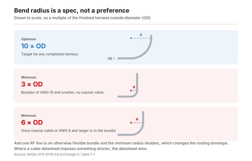
The bend radius for a finished bundle needs to fall within the right parameters, not just fit into the tightest space you can force it into. Table 7-1 in NASA-STD-8739.4A puts the optimal radius at 10× the outside diameter (OD) of the completed harness, with a minimum of 3× OD for bundles of AWG 10 and smaller that contain no coaxial cable, or a minimum of 6× OD for bundles with a coaxial cable or a cable that is AWG 8 or larger.
Cable datasheets sometimes impose stricter parameters. If they do, follow those set by the datasheet.
If your bundle includes coaxial cable, this will affect the spec. You’ll need to add one RF line to an otherwise flexible bundle and double the minimum radius, which changes the routing envelope inside the enclosure.
Common problems at this step: branch lengths that are too short, a bend radius below the required minimum, tension landing on the contact instead of the strain relief.
Step 5. Apply Protective Coverings
Any protective coverings are added before the final assembly. Depending on the harness, these might include tape, braided sleeve, convoluted conduit, heat shrink, and grommets. Coverings are used to provide abrasion resistance, bundle discipline, and strain relief at the points where the harness passes through a panel or moves in service.
Common problems at this step: coverings applied over the wrong break-out point, heat shrink not fully recovered, a conduit that ends short of the panel it was meant to protect.
Step 6. Electrical Testing
Every net should be checked for continuity before the harness leaves the bench. For certain harnesses, insulation resistance and dielectric withstand testing may also be required.
Common problems at this step: skipping testing on “simple” harnesses, resulting in a faulty setup.
Step 7. Inspect, Label, and Pack
After harness has successfully been tested, it goes through a final visual inspection based on the acceptance class specified on the drawing. Its legs and connectors should be given identification labels or heat-shrink markers. Finally, the harness should be coiled and packed so its contacts aren’t loaded in transit.
Common problems at this stage: no labels added, so the installer has to guess at the right procedure.
How Are Wire Harnesses Tested?
Assemblies are verified using three electrical tests, then a function test at the end of the build. All assemblies are subject to continuity testing, which confirms that every net starts and ends at the right pin. This catches any miswiring, open crimps, and contacts that were never seated. Some assemblies also require insulation resistance testing, which checks that the nets are isolated from each other and from the shield or chassis. Finally, dielectric withstand testing (usually called hipot) applies voltage that is well above working voltage to make sure the insulation holds up even under those extreme conditions.
On a harness with more than a handful of nets, 100% continuity testing on every unit should be the default, instead of just testing a sample. The test takes seconds on a fixture and it can catch a failure that would be much more expensive to fix if it’s only found later, when the harness has already been installed in an enclosure.
Is Wire Harness Assembly Manual or Automated?
It is mostly manual, and that’s because many of the steps are difficult to automate. The initial steps (cutting, stripping, crimping, partial connector insertion) are repetitive single-wire operations that machines can do faster and more consistently than people. But the board work itself is better done manually. The Robotics review cited above names routing a limp bundle through a fixture, dressing branches, taping break-outs, and placing cable ties as the tasks with the highest potential for automation precisely because they still need R&D. Routing and connector mating are the only board tasks with working automated solutions, and neither is general-purpose enough to take over a high-mix line, so they’re often still done by hand.
So with most industrial products, the front end gets automated but the board work stays manual. High-mix, medium-volume electromechanical products are almost never worth automating past the crimp press.
The exception is automotive tier suppliers with production runs in the hundreds of thousands for a single harness variant. For them, the economics justify a heavier reliance on automation.
What IPC/WHMA-A-620 Requires (And Why You Should Specify a Class)
IPC/WHMA-A-620 is maintained jointly by the IPC and the Wiring Harness Manufacturer’s Association. It is the only industry-consensus international standard for the performance and acceptance of cable and wire harness assemblies. The standard defines acceptance criteria for stripping, crimping, soldering, connector assembly, wire and cable securing, marking and testing, with photographs and illustrations for target, acceptable, and defective conditions at each one.
Assemblies are classified according to three classes. Class 1 covers general electronic products, Class 2 covers dedicated-service products where continued performance matters, and Class 3 applies to high-performance products where downtime is not tolerable, including life-support and military equipment.
An assembly’s class is determined in part by its intended environment. For example, we build a benchtop educational device meant for use in a benign environment, which falls under Class 1. But a commercial sauna heater that we build needs to live in sustained heat, which makes it a Class 2 device and changes the types of wires and sleeves used in the assembly. Then there’s an IoT light used for underground mining operations, which is Class 3 because it needs to survive moisture, vibration, and handling with thick gloves.
Name the right class on your drawing. That’s the easiest way to control harness quality, because it corresponds to documented acceptance criteria that both sides can inspect against. It also tells the supplier which inspection load to price. If you don’t specify a class for your harness, the supplier will build it according to their default workmanship is, and you may be disappointed with the results when the product goes through your incoming inspection.
Design Choices That Reduce Harness Cost
Your design has a significant impact on harness cost. Here are five features to watch for.
Connector count. Every connector adds contacts that need to be crimped, cavities to populate, and nets that must be tested. If you’re able to consolidate two 6-way connectors into one 12-way connector, you’re removing an entire mating interface and the potential failure point it introduces.
Splices. In-line splices are slow to make, awkward to inspect, and difficult to repair. If your routing allows it, land branch points at connectors instead to simplify the assembly and lower your costs.
Wire gauge variety. If your harness has four different gauges, making it will require four tool setups and four die sets. On a low-current signal harness, you can usually get away with just two gauges, which reduces the overall assembly time and expense.
Branch length tolerances. If your tolerances are tighter than the routing actually requires, this will result in a more expensive form board and longer assembly time for the board operator.
Missing service loops. A missing service loops means a connector can’t be disconnected without tension on its contacts. You can add slack after the fact, but that means rebuilding the harness.
Most of these problems will show up in a DFM review. We have a team of 40+ engineers that provide a free review at the quote stage, so you can catch these issues before you commit to form boards and tooling.
Need a harness for your product? Send us your harness drawing, wire list, and BOM, along with the enclosure. Our engineering team will provide a DFM review and a quote that covers both the harness and the full assembly. Request a quote.
Frequently Asked Questions
What Is a Wire Harness Assembly?
A wire harness assembly is a sub-assembly that consists of wires, terminals, connectors, and protective coverings. Since it is built separately from the finished product, the harness can be tested and inspected before it gets installed in the enclosure.
What Is the Difference Between a Cable Assembly and a Wire Harness?
A cable assembly is a single jacketed cable that terminates at both ends. A wire harness, on the other hand, is a branched bundle of wires that are routed to multiple endpoints and held together with tape, ties, or sleeves. Harnesses also have break-outs and multiple connectors, while cable assemblies usually run point-to-point.
What Are the Parts of a Wire Harness?
The basic components of a wire harness are the conductors, terminals or contacts, connector housings, along with any protective coverings (e.g. tape, braided sleeves, convoluted conduits, heat shrinks, grommets) that are needed. and protective coverings. There may also be add-ons like clamps, cable ties, strain reliefs, in-line splices, fuses or fuse holders, or ferrite cores. And there could be identification labels or heat-shrink markers on each leg.
How Long Does It Take to Assemble a Wire Harness?
It depends on the net count and how complex the branches are. A simple two-connector harness can be put together in minutes, but a multi-branch industrial harness with dozens of nets could take over an hour to assemble. Manufacturers can speed up these timelines by automating the cutting, stripping, and crimping that is done in the first steps of the assembly process.
Does a Wire Harness Need to Be Tested?
Yes, continuity testing is standard for every net on each harness that is produced. Insulation resistance and dielectric withstand testing may also be needed if the working voltage, safety approval, or acceptance class requires it. Even when it’s not required, testing is a simple and affordable way to catch failures early in production, when it’s easier and cheaper to fix them.
What Standard Applies to Wire Harness Assembly?
IPC/WHMA-A-620 is the industry-consensus standard for cable and wire harness assembly acceptance, with different requirements for Class 1, 2, and 3 assemblies. Aerospace and defense programs often specify NASA-STD-8739.4 as the applicable standard, or a customer-specific workmanship document. Automotive programs typically add OEM-specific requirements.