
Plastic Part Design for Injection Molding: DFM Guide
- Key Takeaways
- Design Adjustments Cost More Than Process Adjustments
- Nominal Wall Thickness
- How Much Draft Does Your Injection Molded Part Need?
- Ribs, Bosses, and Gussets
- Corner Radius
- Undercuts
- Gate Location and Weld Lines
- What Tolerances Can Injection Molding Actually Hold?
- Material Choice Changes Everything
- Pre-Tooling Design Review Checklist
- Frequently Asked Questions
- Get a DFM Review Before You Commit
Plastic part design for injection molding means shaping a plastic part so it fills, packs, cools, and ejects from a steel tool without any defects.
There are six aspects of a design that ensure that the plastic part will come out as intended.
The most important variable is arguably wall thickness. Get this one wrong and you won’t be able to do anything at the press to save the part.
The other five elements are: enough draft to release, rib size (so they stiffen without sinking), radiused internal corners, minimal undercuts, and tolerances specified to what molding can actually hold.
In this guide, we’ll go over each of these elements in detail so you can design an injection molding part that meets all the right parameters.
Key Takeaways
Fixing a plastic part at the design stage is far cheaper and faster than fixing it once the tool has been cut.
When designing a part, the main consideration is wall thickness, since uneven wall thickness can result in sink and warping.
Consider the material as part of your design – amorphous and semi-crystalline resins shrink differently and your tool should accommodate this.
Weld lines should located away from load-bearing features or cosmetic surfaces.
Table of Contents
- Key Takeaways
- Design Adjustments Cost More Than Process Adjustments
- Nominal Wall Thickness
- How Much Draft Does Your Injection Molded Part Need?
- Ribs, Bosses, and Gussets
- Corner Radius
- Undercuts
- Gate Location and Weld Lines
- What Tolerances Can Injection Molding Actually Hold?
- Material Choice Changes Everything
- Pre-Tooling Design Review Checklist
- Frequently Asked Questions
- Get a DFM Review Before You Commit
Design Adjustments Cost More Than Process Adjustments
Some defects in plastic molded parts can be fixed by making adjustments to the molding process. The operator can change the melt temperature, injection speed, pack pressure, and cooling time to try and get better results.
Those fixes are usually manageable and won’t cause any significant slowdown to production.
That’s not the case with design problems. When the defects are caused by tool’s design, there’s not much the molder can do. When you’ve got a 6 mm boss meeting a 2 mm wall, no amount of fiddling with the settings on the equipment will get you the results you need.

That’s why getting the design right should be a priority. Changing the part’s geometry after the tool has been cut means welding steel and re-machining the cavity. This typically requires two to four weeks and can be rather costly. But if you catch it at the design stage, making those changes in CAD only takes an afternoon.
To save yourself the cost, trouble, and delay that comes with an inadequate tool, spend some time getting the initial design right. Work through the following sections, and do them in order, because each decision affects the one that comes after.
Nominal Wall Thickness
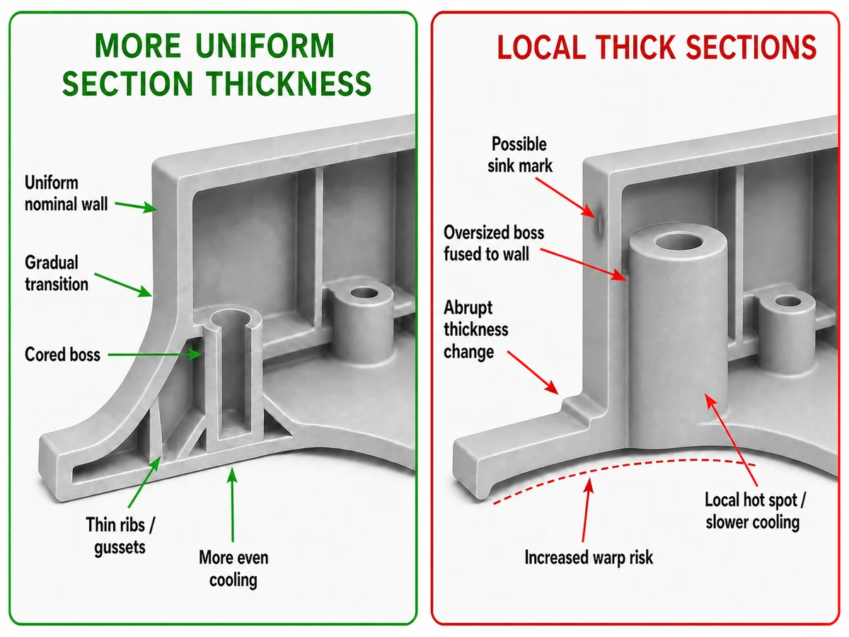
Uniform wall thickness is what prevents sink and warp, which makes it the first thing to get right in any molded part design.
To get this right, pick one nominal wall for the part and hold the thickness within about ±10% variance along its entire length.
If you can’t avoid bigger changes in thickness, make sure to taper the transition over at least three times the wall thickness. This will work better than stepping it.
If you have a section that has to be thick (like a structural mount or a hinge boss), core it out from the back and use ribs to replace the lost stiffness.
Here’s a table that will get you started.
| Resin | Typical nominal wall | Mold shrinkage | Design note |
|---|---|---|---|
| ABS | 1.2–3.5 mm | 0.4–0.7% | Predictable and forgiving; a good first choice for housings |
| Polycarbonate | 1.0–3.8 mm | 0.5–0.7% | Notch-sensitive; radii matter more than usual |
| PC/ABS | 1.2–3.5 mm | 0.5–0.7% | Balances PC toughness with ABS moldability |
| Polypropylene | 0.8–3.0 mm | 1.0–2.5% | High shrinkage; expect warp on large flat faces |
| Nylon (PA6/PA66, unfilled) | 0.8–3.0 mm | 1.0–2.0% | Moisture uptake shifts dimensions after molding |
| 30% glass-filled nylon | 1.0–3.0 mm | 0.3–0.5% | Anisotropic (~0.3% along flow, ~1.0% across it) |
| POM (acetal) | 0.8–3.0 mm | 1.8–2.5% | High, uniform shrink (size the tool accordingly) |
Shrinkage
Shrinkage can vary based on fill percentage, wall thickness, and gate pressure.
The shrinkage value is also the number your toolmaker will be using to size the tool’s cavity. If your design has a 0.5% error on a 200 mm dimension, this will result in 1 mm of scrap for each unit.
Flow Length Ratio
Take the flow length into account as well. Every resin has a flow-length-to-wall-thickness ratio. If you exceed that ratio, your tool will cause short shots no matter how hard you push.
For unfilled polypropylene, the ratio will be 250:1 or better. For polycarbonate, it’s closer to a 100:1 ratio. So if you’ve got a 300 mm PC part with a single gate and a 1.2 mm wall, it won’t fill properly. You’ll need a thicker wall, a second gate, or a different resin to make it work.
How Much Draft Does Your Injection Molded Part Need?
An injection-molded part needs a minimum of 1° of draft per side. But that’s only for untextured surfaces in unfilled resin. If your part has more depth, texture, or polish, you’ll need to add more to compensate.
This table covers how different surfaces affect the amount of draft you will need.
| Surface condition | Minimum draft per side |
|---|---|
| Untextured, unfilled resin | 1° |
| SPI A-1 / A-2 high polish | 1.5–2° (vacuum and scratch visibility both increase) |
| Light texture (fine grain) | 3° |
| Heavy grain / deep texture | 5°+ |
| Rib and boss sidewalls | 0.5° minimum (1° preferred) |
| Deep cores and pockets | 1° per 25 mm of depth |
Added Depth
For depth, the rule of thumb is to add 1° of draft per 25 mm (1 inch) of draw depth. Walls with less draft than this can scuff, drag, and eventually gall the tool.
Texture
For texture, add an extra 1° of draft for every 0.025 mm (0.001 in) of texture depth. A moderately deep grain might need up to 5° of draft, even if the designer only penciled in 1° for it.
Texture usually only gets specified after the CAD is frozen and the draft has been finalized. Because of this, you should agree to the SPI mold finish grade and texture depth before you release the geometry.
If you’re ever debating whether to add half a degree to a rib, just add it. The wall variation it introduces is trivial and it will prevent ejector drag marks. Ultimately, it’s better to have a slightly higher degree of draft than is strictly necessary than to have too little.
Ribs, Bosses, and Gussets
Ribs
The base of a rib should be 40–60% of the nominal wall thickness.
If the base exceeds 60%, the extra material will cool after the visible A-surface has already solidified, which will leave a sink mark. If you go below 40%, the rib will be hard to fill and prone to short shots at the tip.
The exact rib-to-wall ratio you need to aim for will depend on the type of polymer you’re using. Semi-crystalline resins (PP, PE, POM, unfilled nylon) shrink hard, so you should keep the rib to 40–50% of the wall thickness if your part will be made using these. But if you’ll be using amorphous resins (ABS, PC, PC/ABS), you can go up to 60%.
Thickness is your main consideration, but here are other parameters to follow for ribs:
- Height: No more than 3× the rib thickness (taller ribs buckle, and they’re difficult to fill and vent).
- Spacing: At least 2× the nominal wall between ribs, so the steel between them can be cooled.
- Base fillet: 0.25–0.5× the rib thickness (larger fillets reduce stress concentration but add mass, which can result in sink).
- Draft: A minimum of 0.5–1° per side.
Crush Ribs
These values don’t apply to crush ribs, because crush ribs are designed to be undersized. Crushed ribs are placed on the inside of a hole or the face of a boss so they’ll deform during assembly. That way, they can hold a press-fit insert, lens, or shaft without using an adhesive. This works because a thin rib will yield locally instead of hoop-stressing the whole boss and cracking it.
Bosses
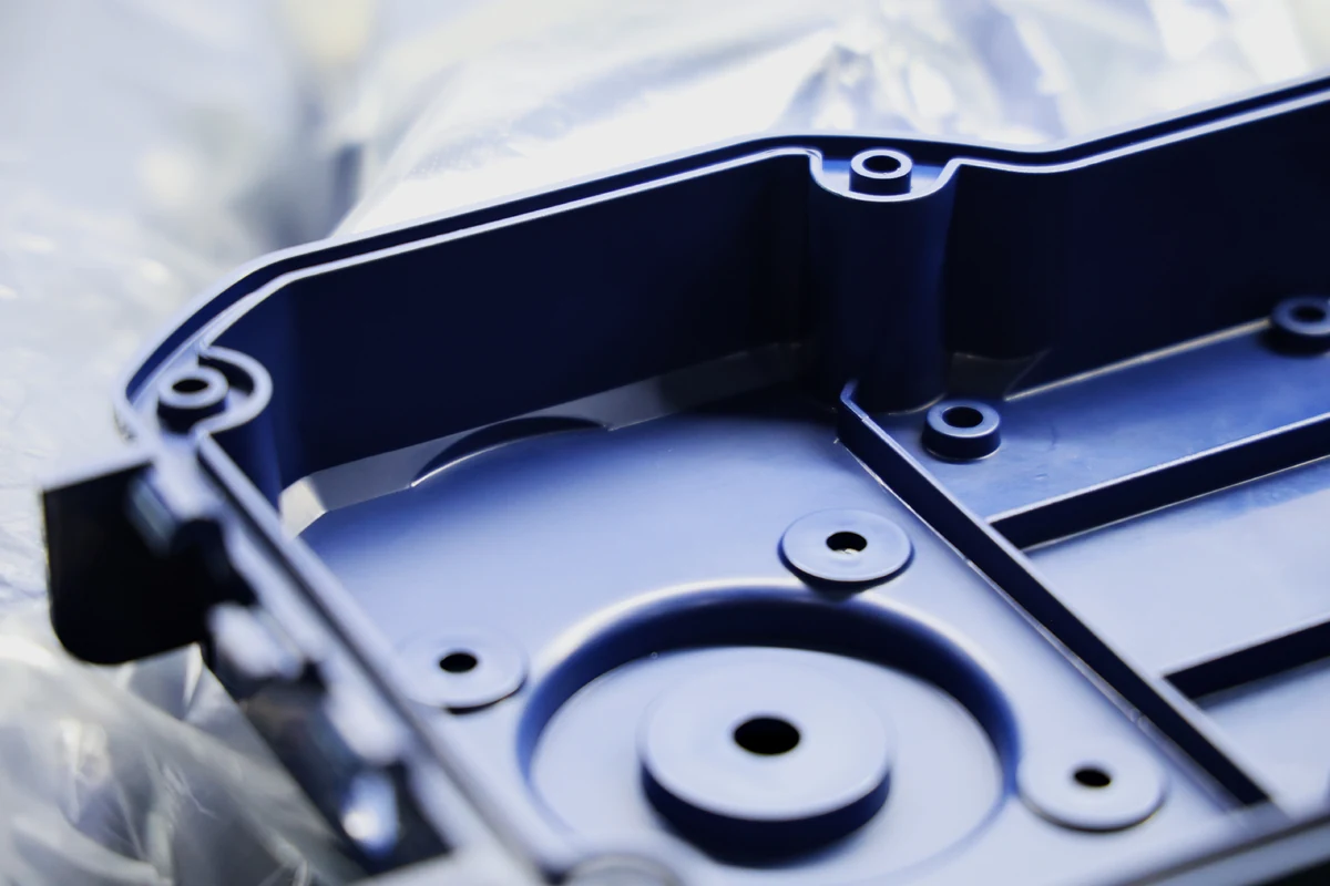
Size the outside diameter of a boss so it’s roughly 2–2.4× the screw’s major diameter. Keep the boss wall near 60% of the nominal wall. Core the boss from the base so the section stays thin.
Never fuse a boss directly into a sidewall. This creates a merged section that will be too thick and will sink. Stand the boss off and tie it back with a gusset instead.
If a boss sits behind a cosmetic A-surface, you have two options. You could core the back of that surface, or you could accept the sink and specify a texture that hides it. Like most things, making this decision during a design review is far cheaper than discovering it during the first-article inspection.
Corner Radius
Every internal corner needs a radius that is at least 0.5× the nominal wall. In areas where the part will be subjected to load, a radius of 0.75× is preferable.
Then set the outside radius so it equals the inside radius plus one wall thickness. This will keep the material thickness uniform through the corner. Deviate from this and the corner will become a thick section that causes sink and warp.
The radius of a corner can also affect where stress gets concentrated. Per Envalior’s design guidance on radii and chamfers, an inside radius below about 0.1× the wall pushes the stress concentration factor to 3, while a radius of 0.5× wall brings it down to roughly 1.5. Past that point, you’re adding material but getting very little return for it. Below it, you’re creating a crack initiation site that could cause your part to fail sooner.
If you’re designing for polycarbonate or glass-filled nylon, avoid any sharp corners. Polycarbonate is notch-sensitive. In filled nylon, fibers orient around the corner and leave a resin-rich weak zone. When designing for those materials, treat 0.75× wall as the minimum corner radius.
Sharp corners can also affect the flow. Melt picks up shear as it negotiates a sharp turn, and this results in residual stress in the finished part.
Undercuts
An undercut is any feature of the part that prevents it from pulling straight off the core. These features include side holes, snap windows, external threads, and latches.
All of these undercuts are moldable, but each will cost you a slide, a lifter, or a collapsing core. And that means more tool cost, another moving component to maintain, a witness line on the part, and a potentially longer cycle.
Your best bet is to try to design the undercut out, instead of simply accepting it.
Here are five ways to do that, in order of desirability:
- Convert the undercut to a through-hole. Most snap-fit windows can become open slots that are molded by mating steel from both mold halves (a shutoff).
- Move the feature to the parting line. Reorienting a latch by 90° sometimes eliminates the action entirely.
- Bump it off. Shallow undercuts on ductile resins (like PP or PE) can strip off the core during ejection if the part has room to flex. How well this works varies, so be sure to validate it on a prototype tool.
- Use a lifter for internal undercuts. This is cheaper and more compact than a slide.
- Use a slide for external undercuts. This is not an ideal solution, but is suitable if none of the other four options are relevant or feasible.
Machine Design covers the mechanics of each option in more depth.
Make sure every undercut is justified before you send the tool to be made. Often, they’re just carried over from a machined prototype and aren’t genuinely needed.
Gate Location and Weld Lines
The gate location is decided when you’re designing the mold. But it’s constrained by other decisions you make in the part.
Gate into the thickest section and let material flow from thick to thin. If you gate into a thin section, the thick region downstream will pack out badly. That’s because the thin gate area freezes off before the packing pressure can reach the heavy section. That results in a sink mark you can’t get rid of.
Weld lines form wherever two flow fronts meet and re-join. This happens behind every hole, every core pin, and every time flow splits around an obstruction. A weld line is always weaker than the surrounding material. This is even worse with glass-filled grades because fibers orient parallel to the weld interface instead of bridging it, and the strength penalty grows as the fiber content rises. On a 30% glass-filled nylon, a weld line sitting across a load path is a baked-in failure point.
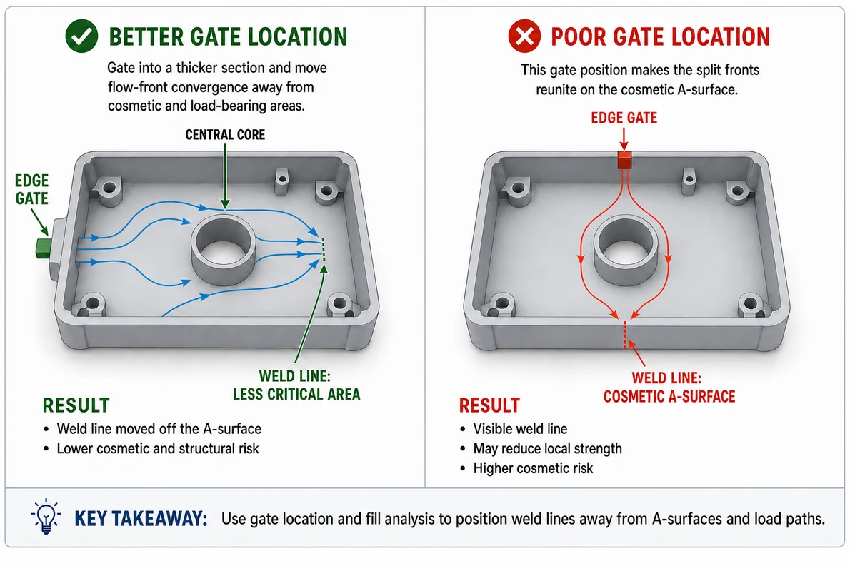
Ask your molder for a mold flow analysis before your tool design is finalized. It only takes a day and it will show you exactly where the fronts meet, where air will get trapped, and from which gate the part will fill. Local cooling and wall geometry interact strongly in thin-wall parts, which is precisely the kind of thing you can catch early by running one of these simulations.
If you want to know how the machine, the mold, and the cycle all work together, check out our plastic injection molding process guide. If you need to diagnose a defect you’re already seeing in your part, see our page on injection molding defects and their root causes.
What Tolerances Can Injection Molding Actually Hold?
Here are some practical considerations for the drawing itself:
- Identify the dimensions that actually matter, like mating interfaces, sealing faces, or hole patterns that bolt to something. Tolerance those tightly and apply a general tolerance class to everything else.
- Dimensions contained within one of the mold halves will hold far better than dimensions that cross the parting line or span a slide. Where possible, put a critical interface entirely in one of the halves.
- Tolerance is based partly on the material you’re molding. Semi-crystalline resins with 1.5–2.5% shrinkage cannot hold as much as an amorphous resin at 0.5% can.
- Nylon absorbs moisture and grows after molding. If you’re dimensioning a nylon part, specify whether the measurement is taken dry-as-molded or conditioned.
Drawings with a blanket tolerance (±0.05 mm on every dimension) will either get quoted high or get quoted with caveats. They tell the molder you haven’t decided what matters, so they’re forced to assume everything does and will price accordingly.
Material Choice Changes Everything
Choose the resin before you finalize the part geometry, so the design accounts for how that material shrinks.
The distinction that matters most is between amorphous and semi-crystalline resins.
Amorphous resins (ABS, PC, PC/ABS, PS, PMMA) shrink 0.4–0.7% and shrink about equally in every direction. They hold tighter tolerances, warp less, and are the right choice when you need a flat panel or a precise mating interface.
Semi-crystalline resins (PP, PE, PA, POM, PBT) shrink 1–2.5%, and often shrink unevenly. But they bring chemical resistance, fatigue life, and living-hinge capability that are superior to amorphous grade resins. They warp more, and that’s something you’ll have to design around.
Glass-filled materials complicate the design even further. A 30% glass-filled nylon shrinks roughly 0.3% along the flow direction and around 1.0% across it. That differential is enough to bow a flat panel into a saddle. Rib direction and gate position determine the orientation of the flow, so use these to create a better structure for your part. If you need a large panel to be flat, change the resin before you start adding ribs to fight the warp.
Consult our overview of plastic injection material options to see the trade-offs by application.
Pre-Tooling Design Review Checklist
Here’s a checklist to run through before finalizing a design and getting the tool made.
- The nominal wall’s thickness is held to ±10% variation along its entire length, with tapered transitions of 3× wall or more.
- There are no isolated thick sections, and any heavy areas are cored out and ribbed.
- Draft has been applied to every vertical face, and the amount of draft has been checked against the final texture spec.
- The base of ribs are 40–60% of the nominal wall thickness (or 40–50% for semi-crystalline resins). The height of ribs is set to ≤3× rib thickness and spacing is ≥2× wall.
- All bosses are cored, placed away from sidewalls, and tied back with gussets.
- Every internal radius is ≥0.5× wall. Every external radius is measured as the internal radius plus one wall.
- Every undercut included in the design is justified or has been converted to a shutoff or parting-line feature.
- The parting line is chosen and its witness line is placed at an acceptable location.
- The location of ejector pins has been reviewed against cosmetic surfaces.
- The gate location has been verified with the molder, and the flow runs from thick to thin.
- All weld lines have been identified and are kept off load paths and A-surfaces.
- Tolerances for critical dimensions are called out (a general tolerance class has been assigned to cover the rest).
- The resin grade and shrinkage rate have been confirmed against the supplier’s datasheet.
Frequently Asked Questions
What is the minimum wall thickness for injection molding?
Most production parts run 0.8 to 3.0 mm depending on the resin, with 2.0 to 2.5 mm typical for housings. Thinner walls are possible but need thin-wall tooling, higher injection pressures, and a short flow path. To find your practical minimum, divide the part’s flow length by the resin’s maximum flow-length-to-wall ratio.
Why do injection molded parts need draft angles?
Without any draft angles, the part will drag across the steel when it’s ejected. This can cause scuff marks, stress whitening, and wear out the tool more quickly. One degree of draft per side is the minimum on untextured surfaces. Textured surfaces need an extra degree for draft for every 0.025 mm of texture depth.
What is the most common plastic part design mistake?
Walls that don’t have uniform thickness along their entire length. Changes in thickness can result in sink marks, warpage, short shots, and internal stress. Even worse, it can’t be fixed at the press, so the tool has to be redesigned or modified. Thick bosses fused into thin walls and un-cored structural sections are the two most common versions of this.
How do you prevent sink marks in a molded part?
Keep the base of ribs at 40–60% of the nominal wall thickness. Core out any section thicker than the surrounding wall, gate into the thickest area so packing pressure reaches it, and avoid merging bosses directly into sidewalls. If you need to place a thick feature behind a cosmetic face, core the back of that face or specify a texture that masks the depression.
What tolerances can injection molding hold?
General tolerances are set by DIN ISO 20457:2021-06. This standard specifies tolerance groups based on nominal size, material shrinkage, mold complexity, and process stability. Amorphous resins have tighter tolerances (0.4–0.7% shrinkage) than semi-crystalline resins (1–2.5% shrinkage). Specify tolerances for the most critical dimensions and rely on general tolerances for everything else.
Get a DFM Review Before You Commit
Every design issue is cheap to fix in CAD and expensive to fix in hardened steel. Komaspec’s engineering team runs design for manufacturability reviews on plastic parts before tooling is quoted. This includes wall thickness, draft, gate and weld line placement, tolerance feasibility and material selection, with the mold flow analysis to back it up. Send us your model and we’ll provide a marked-up DFM report and a quote for plastic injection molding.