
Injection Molding Defects: Causes, Fixes, and Prevention
- Key Takeaways
- How to Diagnose an Injection Molding Defect
- 12 Common Injection Molding Defects
- Short Shot
- Flash
- Jetting
- Sink Marks and Voids
- Warpage
- Weld Lines
- Flow Lines
- Splay
- Burn Marks
- Delamination
- Ejector Marks
- Process Problems vs. Design Problems: Who Owns the Issue?
- FAQ
Injection molding defects are caused by problems with the process settings, the mold, the materials, or the part's design.
While any of these could compromise your product, design issues are the most important ones to prevent and fix. A defect in the design will reproduce itself across the entire production process and across every material lot used. It's a problem that's baked into the part or cut into the tool, and no amount of parameter tuning will remove it.
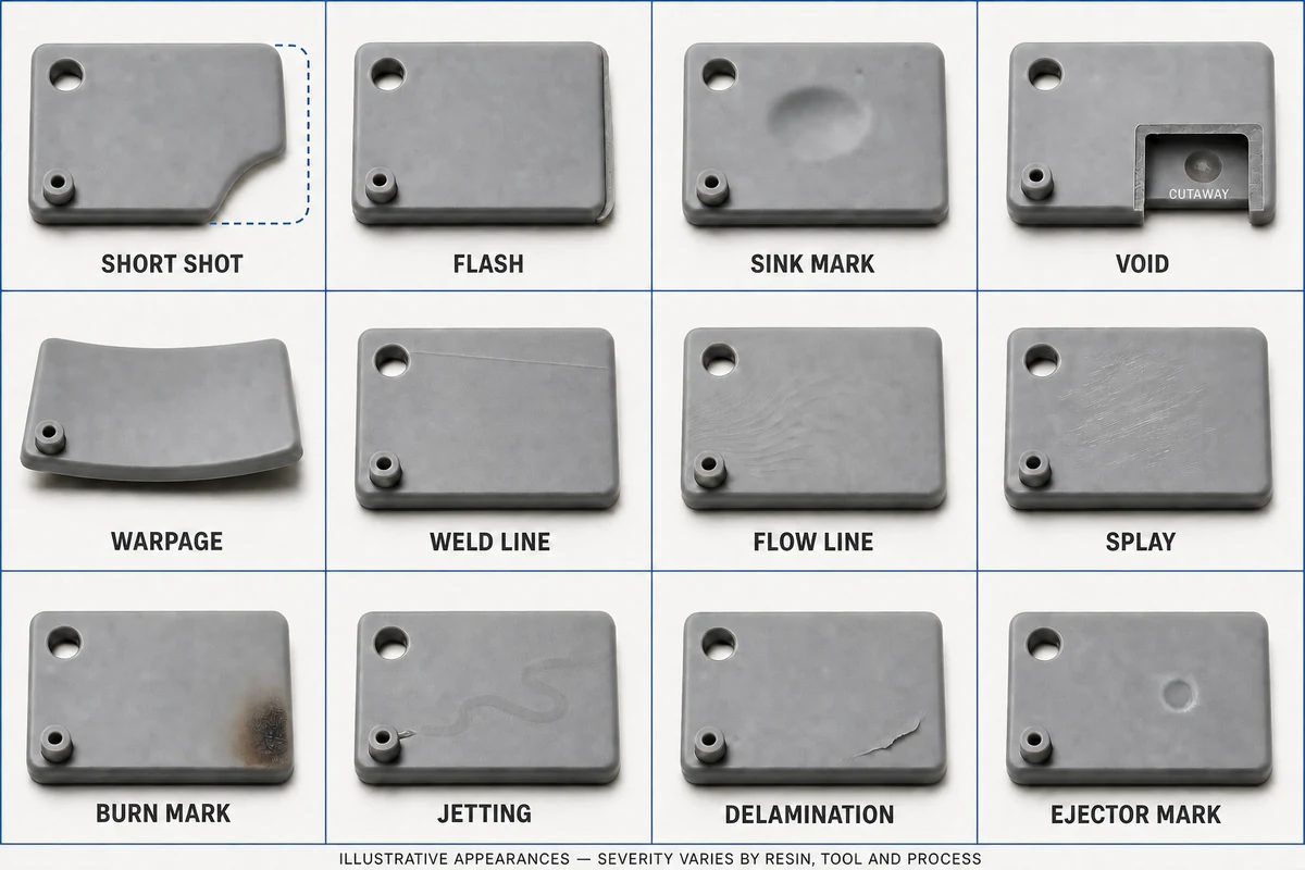
This guide covers the 12 injection molding defects that account for most rejected parts.
In each case, we'll go over fixes the molder can implement at the press and those that should have been handled at the design phase. Those are different conversations with different owners, and we'll be covering both.
Key Takeaways
The most common injection molding defects are sink marks and short shots.
The most common root cause across defects is non-uniform wall thickness.
Chronic defects that show up across runs and material lots are usually due to the design, not the process used to mold the part.
Conducting a design review to identify and prevent defects at the design or tooling stage is far more cost-effective than trying to fix issues during production.
Table of Contents
How to Diagnose an Injection Molding Defect
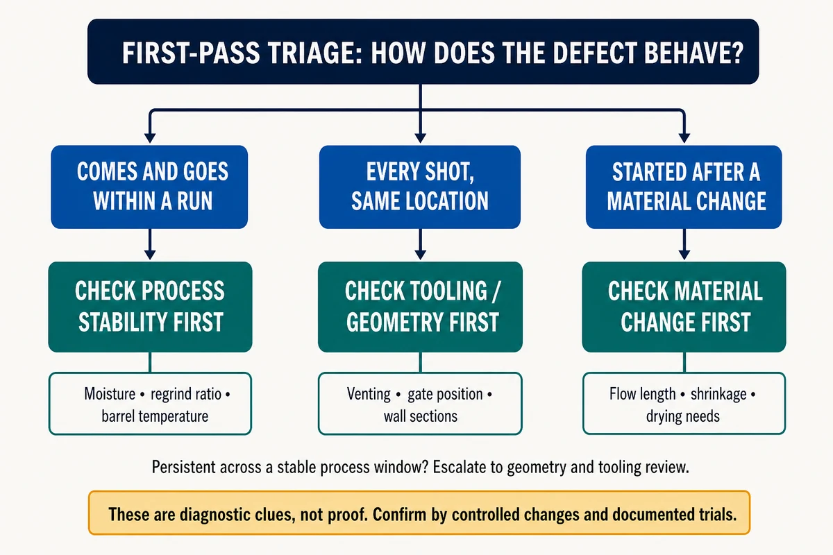
Start by identifying when and where the problems show up.
Intermittent defects that come and go during a run are probably due to process drift or material variation (e.g., moisture, regrind ratio, barrel temperature).
Defects that appear on every shot in the same location point to a problem with the mold or the design (e.g., venting, gate position, wall sections).
Defects that only appeared after a change in material are likely due to the resin.
This step matters because it can save you from wasting time trying to troubleshoot a design problem by adjusting your process settings.
12 Common Injection Molding Defects
| Defect | What it looks like | Most common root cause |
|---|---|---|
| Short shot | Incomplete part, missing features | Insufficient flow: thin walls, low melt temp, poor venting |
| Flash | Thin fins at parting line or ejector pins | Worn parting line, low clamp force |
| Sink marks | Depressions over ribs, bosses, thick sections | Thick sections shrinking after the gate freezes |
| Voids | Bubbles inside thick sections | Same shrinkage as sink, trapped internally |
| Warpage | Twisted or bowed part | Differential shrinkage: uneven walls or cooling |
| Weld lines | Visible seam where flow fronts meet | Flow splitting around holes/cores and rejoining cold |
| Flow lines | Wavy streaks near the gate | Slow injection, cold melt or mold |
| Splay | Silvery streaks dragged across surface | Moisture in the resin |
| Burn marks | Black/brown scorching at end of fill | Trapped air compressing and igniting (diesel effect) |
| Jetting | Squiggly worm-like strand from the gate | Melt shot into open cavity without impingement |
| Delamination | Surface peels in layers | Contamination or incompatible material mix |
| Ejector marks | Glossy or stressed circles at pin locations | Ejecting too hot or too fast, undersized pins |
Filling Defects
Short Shot
A short shot means the mold cavity doesn't fill completely.
At the press, this can usually be fixed with a higher melt temperature, more injection pressure or speed, or a bigger shot size.
If those adjustments don't remedy the issue, the problem is somewhere upstream. You might be dealing with walls that are too thin for the material's flow length, a gate that's too small or too far from the thin region, or vents that cause the trapped air to block the flow front.
Another problem might be the material. Glass-filled resins shorten the flow length substantially, so a design that filled just fine using unfilled PP could short-shoot when you switch to 30% glass nylon.
Flash
Flash is the opposite of a short shot. It happens when the material escapes the cavity and seeps into the parting line, vents, or ejector clearances.
If you're using the right tool, the problem might be low clamp force or overpacking.
But if flash persists on one tool with adequate tonnage, it means the parting line is worn or was never fully seated. In that case, the tool needs to be fixed, not the process.
If you're getting flash on every shot with a new mold, the problem is the mold quality. It's worth raising this with the toolmaker rather than accepting a trimming operation for the life of the part.
Jetting
Jetting is a squiggly strand embedded in the part surface near the gate. It happens when the melt is shot through the gate into open cavity space, cooled as a free jet, then gets over-molded by the rest of the fill.
Slowing the initial injection speed helps. But for a long-term fix, adjust the gate placement. The melt should impinge on a wall or core immediately after the gate so it can't travel as a jet.
Shrinkage Defects
Sink Marks and Voids
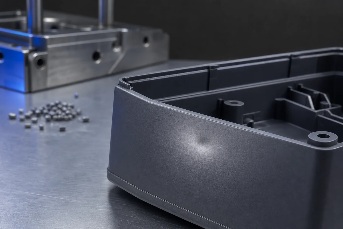
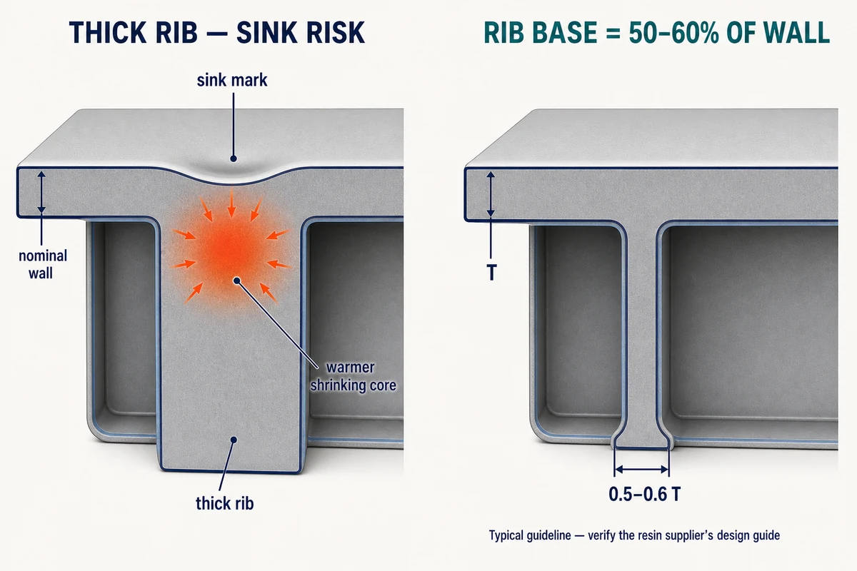
Sink marks and voids are the same defect, but in opposite directions. Thick sections cool last, and when the gate freezes before they've been packed out, the shrinking core either pulls the surface inward (sink) or cavitates internally (void).
Warpage
Warpage happens when one region of the part shrinks more than another, causing the part to twist or bow. Semi-crystalline resins (PP, nylon, POM) warp far more than amorphous resins (ABS, PC) because crystallization amplifies these differences in shrinkage.
To fix this at the press, you can balance mold-half temperatures and extend cooling time.
But if your product experiences chronic warpage, the issue is the part's design. It might be non-uniform walls, long unsupported flat sections, or fiber orientation in glass-filled grades.
If your part needs to be dead flat, this requirement should be part of the design review. That will give you an opportunity to choose ribbing, gate positions, and materials that will prevent the part from warping.
Surface and Appearance Defects
Weld Lines
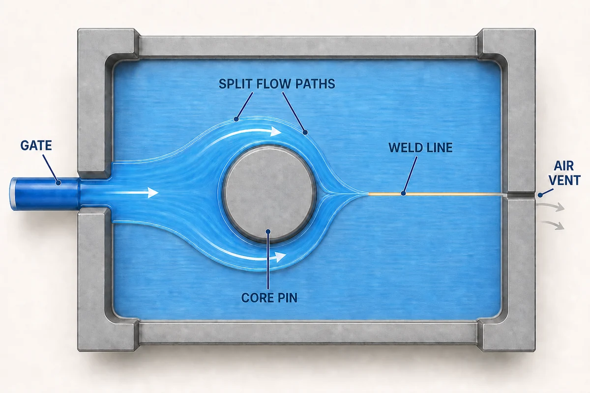
Weld lines (knit lines) are seams that form where the flow front splits (around a hole, a core pin, or a boss, for example) and then rejoins after the fronts have already cooled.
A hotter melt, faster injection, and a vent at the weld location can resolve this.
Flow Lines
Flow lines are wavy, off-color streaks that track along the flow path, usually near the gate. They happen where melt has been cooled against the mold wall between pressure waves.
This can usually be fixed by raising the melt and mold temperatures and speeding up the injection.
If the issue still persists, enlarge the gate or move it so the flow path doesn't stall across a cosmetic face.
Splay
Nine times out of ten, splay (silver streaks) is due to moisture. Water that's absorbed by the resin flashes to steam in the barrel and gets dragged across the part surface, leaving silvery streaks. Hygroscopic resins (nylon, PC, PBT, and to a lesser degree ABS) must be dried to the supplier's specified moisture content before molding. RJG's guidance on moisture-related defects clarifies that drying time and temperature both matter, not just one.
But what if you're dealing with splay even after properly drying the resin? Then it's probably caused by melt degradation (barrel too hot, residence time too long) or shear at an undersized gate.
Burn Marks
Burn marks are due to the diesel effect. Air trapped at the end of fill gets compressed fast enough to auto-ignite, which scorches the plastic.
Plastics Engineering calls this a venting problem. Slowing the last 5–10% of the fill gives air enough time to escape.
Paulson Training points out that burns can also happen when excessive clamp force pinches vents closed.
Either of those solutions might remedy the problem. But if burns keep appearing at the same corner, that corner needs a vent, and that's a fix for the toolroom.
Delamination
Delamination is when the surface peels off in flakes or layers. The problem here is contamination. It could be an incompatible resin mixed in (a PP regrind fraction in an ABS run will do it), excessive mold release, or degraded material.
With a delamination issue, start by fixing the material handling, not adjusting the machine settings.
If the issue continues even with clean material, this suggests the melt temperature is far too low or you've got a moisture problem.
Ejector Marks
Ejector marks are glossy or whitened circles where pins pushed on a part while it was still too hot or too soft.
Longer cooling, a gentler ejection speed, or more/larger pins can spread the load to help prevent this issue.
If cycle time can't stretch, then the pin layout was undersized for the part's ejection forces. This is yet another issue that's cheap to fix during the tool design but expensive to remedy in production.
Process Problems vs. Design Problems: Who Owns the Issue?
For the most part, process adjustments are the right fix for marginal defects or issues that only show up during part of a run. With chronic defects, it's typically something in the geometry or the tooling, so it needs a design fix.
Or to break it down differently:
- The molder is responsible for issues with melt/mold temperature, injection, packing profiles, drying, and vent maintenance.
- The toolmaker is responsible for anything to do with parting-line condition, venting, gate size and position.
- The designer owns matters related to wall uniformity, rib ratios, boss coring, and the location of weld lines.
Defects are always cheaper to prevent before the tool exists. A DFM review that flags a rib with a 100% thickness compared to the wall or a weld line that lands across a snap-fit will let you nip the problem before any tooling is produced, instead of scrambling to fix it after it shows up in T1 samples.
This is also why you should ask suppliers how they document and resolve defects. Working with a molder that adheres to strict quality management means they will treat a recurring defect as something that needs corrective action, instead of passing the buck so it has to be dealt with at the press.
Fighting a recurring defect, or want the design reviewed before the tool is cut? Send Komaspec your part files for a DFM review. Our engineering team flags sink, warpage, and weld-line risks at the design stage, where fixing them costs a revision instead of a retool.
Frequently Asked Questions
What is the most common injection molding defect?
Sink marks and short shots are the most frequently reported defects. And the most common root cause across all defects is non-uniform wall thickness. This one design issue is responsible for sink marks, voids, warpage, and fill problems. A design with uniform walls and properly sized ribs will prevent many of these defects.
Can injection molding defects be fixed after molding?
In most cases, no. Flash can be trimmed and some cosmetic marks can be polished away. But common defects like sink marks, warpage, weld lines, splay, and voids are permanent. Trying to fix them after the part has been molded adds cost and only hides the problem instead of solving it. The most cost-effective solution is to find the root cause and fix it where it originates (at the press, the tool, or in the design).
What causes sink marks in injection molding?
Thick sections (usually rib or boss junctions) that keep shrinking after the gate freezes and can no longer be packed. The surface pulls inward over the thick spot, creating a sink. Packing harder can compensate for this somewhat, but the only durable fix is keeping rib base thickness at 50–60% of the nominal wall, and coring out any thick features.
How do you stop parts from warping?
Balance cooling between mold halves and extend cooling time at the press. If warpage persists, it's likely a problem with the geometry, like non-uniform walls, unsupported flat spans, or fiber orientation in filled grades. Semi-crystalline resins like PP and nylon warp the most, so choosing the right materials can also help minimize warping.
What's the difference between splay and flow lines?
Splay is silvery streaks dragged in the flow direction. They're caused by gas – in most cases, steam from undried resin. Flow lines are wavy, off-color rings or streaks near the gate. They're caused by the melt cooling between pressure waves. Splay is fixed in the dryer. Flow lines are fixed with temperature, speed, or gate changes.