
Insert Molding: Process, Applications, and Design Guide
- Key Takeaways
- What Is Insert Molding?
- How Does the Insert Molding Process Work?
- Insert Types and Materials
- Design Guidelines for Insert Molding
- When Insert Molding Is the Wrong Choice
- Where Insert Molding Is Used
- Insert Molding vs. Overmolding
- FAQ
Insert molding is an injection molding process in which a pre-formed component (usually made of metal) is loaded into the mold and then plastic is injected around it. When the molten plastic solidifies, it creates a single part with the component embedded into it.
Insert molding is used to embed threaded bosses in plastic housings, electrical terminals in connector bodies, and bushings in a molded part.
But how does it work, and what kind of components can be used?
In this guide, we'll go over the insert molding process, design rules to follow, and when insert molding is the wrong choice.
Key Takeaways
Insert molding is an injection molding method that is used to embed an insert into a plastic body, creating one single part.
Insert molding is commonly used to embed threaded inserts, electronic components, and magnets.
It is more expensive than standard plastic molding, mainly due to specialized tooling and the labor needed to load inserts into the mold.
Most inserts are made of metal, but some plastics, ceramics, and electronic components can also be embedded using insert molding.
Table of Contents
What Is Insert Molding?
Insert molding is a procedure used to embed components into an injection-molded plastic part.
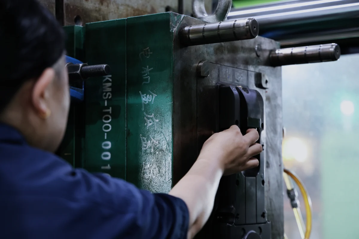
First, the operator (or a robot) places the insert inside the mold. Then, the mold closes and resin is injected into it, using pressure to ensure that it flows around the insert. When the plastic cools, the insert is firmly embedded into the plastic.
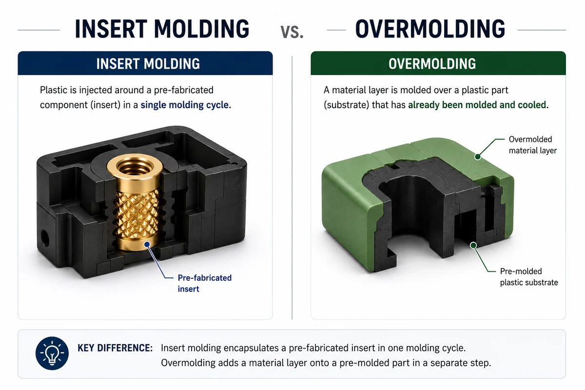
Insert molding is often compared to overmolding, but these are distinct approaches with different purposes and outcomes. While insert molding injects plastic around a pre-fabricated component, overmolding applies a second material over a substrate that has already been molded - in two-shot molding, while that substrate is still hot, which helps the bond.
If you're trying to decide which of the two processes are right for your application, see our detailed breakdown of insert molding vs overmolding.
But one thing to keep in mind is that molten thermoplastic does not chemically bond to metal. Insert molding, then, relies entirely on creating a mechanical hold (with knurls and grooves, for instance) to keep the insert in place.
How Does the Insert Molding Process Work?
Insert molding works just like standard plastic injection molding, except that an insert is added to the mold before the plastic is injected.
Here's a breakdown of the steps involved.
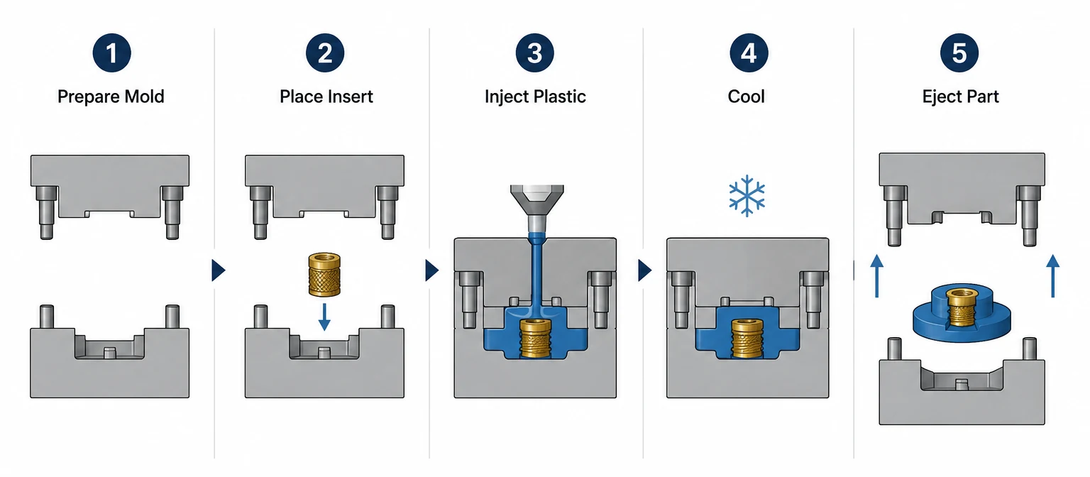
1. Design and prepare the mold. The tool is built with locating features (pins, pockets, or magnetic holders) that hold the insert in the desired position and orientation. It must be able to withstand the injection pressures to avoid shifting the component or deforming the resulting part. Creating these specialized molds is where most of the added tooling cost comes from.
2. Load the insert into the mold. For prototype and low-volume runs, an operator places the inserts by hand between cycles. When scaling up to production volumes, robots can be used to automate this step (whether the automation is worth the added expense will depend on cycle time and the number of inserts added to each part).
3. Preheat the insert (if needed). Metal inserts are sometimes preheated before loading. This prevents the resin from cooling and solidifying prematurely, which can cause issues like knit lines and voids.
4. Inject the resin and allow it to cool. The resin fills the cavity and surrounds the insert. As the plastic cools it shrinks around the insert, which causes it to grip onto the component.
5. Eject and trim the part. The finished part comes out with the insert embedded into it. The operator then trims runners and gates (as they would in any molding operation). Because the component is fully embedded, there is no assembly needed.
Insert Types and Materials
Threaded inserts are the most common type of molded-in insert. These inserts are often made of brass because it machines cheaply, resists corrosion, and its knurled surface forms a strong mechanical lock with the plastic. Stainless steel is more expensive but is the preferred choice when higher strength or chemical resistance are required.
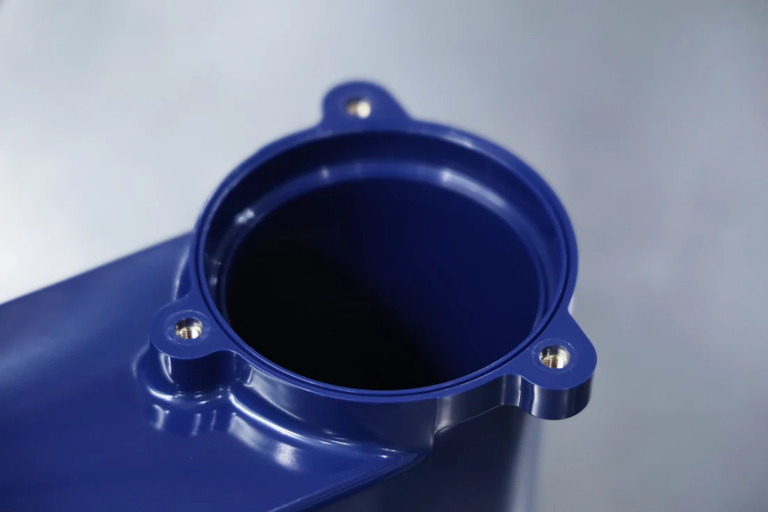
Your choice of resin will depend in part on the design of the insert. Harder, filled materials grip onto knurls well but are more prone to cracking around them. So the knurl depth and boss geometry have to be matched to the material to ensure a suitable result.
Check out our plastic injection materials page for a breakdown of the different types of resin and their individual properties.
Design Guidelines for Insert Molding
Retention Features
Since there's no chemical bond between metal and plastic, the insert needs to be designed with geometrical features the plastic can lock onto.
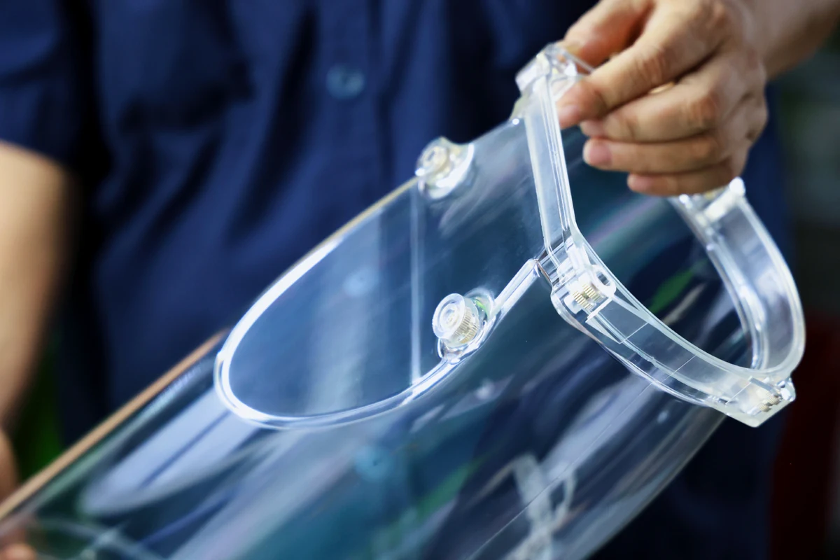
Which features you need depends on the type of hold - SPIROL's design guide for threaded inserts maps knurl styles to torque and pull-out performance. Straight knurling resists rotation but not pull-out. Helical or diamond knurling resists both. Undercuts, grooves, and flanges add axial retention. A smooth cylindrical insert will spin or pull free under load, so if a supplier proposes one, ask what retention feature they're relying on.
Wall Thickness Around the Insert
The plastic that surrounds the insert needs to be thick enough for it to create a solid, durable hold. Too thin, and the plastic risks cracking during cooling or in service.
Insert Positioning and Resin Flow
The tool has to be designed to support the insert against the direction of the fill so it remains stable while being subjected to the pressure of the injection. Gates should be positioned so the flow doesn't hit the insert edge-on, which could cause it to shift or deform.
Long, thin inserts are especially challenging because they deflect under flow pressure, which can result in an insert that measures in-position in the tool but out-of-position in the part.
Differential Thermal Expansion
Metal and plastic expand at very different rates. For example, unfilled nylon 6,6 has a linear expansion coefficient of about 110 × 10⁻⁶/°C while carbon steel has roughly 11 × 10⁻⁶/°C. So pairing them together creates a tenfold mismatch.
Why does this matter? Because a part that's dimensionally fine at room temperature could develop cracks around the insert after thermal cycling, due to the plastic repeatedly straining against the metal insert.
For parts that will undergo wide temperature swings (like automotive or outdoor equipment), glass-filled plastic grades are preferable. These grades cut a polymer's expansion roughly in half. Wide temperature swings are also a reason to keep wall thickness at the generous end of the range.
Dimensions for the part itself should follow ISO 20457:2018, the tolerance standard for plastic molded parts. Features formed by the insert (thread position, pin location) can hold tighter tolerances than molded features, because the insert is a machined component, which is one of the advantages of insert molding.
When Insert Molding Is the Wrong Choice
For certain parts, installing parts after molding is preferable to insert molding. Heat-set or ultrasonic inserts pressed into a molded boss (at roughly 120–175 °C for common resins like ABS and PC) are a better choice when you're dealing with:
Low Production Volumes: The tooling is more expensive for insert molding, and manually loading the inserts stretches out the time for each cycle. Below a few thousand parts a year, using a standard mold and adding the insert after molding will usually be more affordable.
A High Scrap Risk: If a short shot or a flash-through could scrap the insert along with the plastic, post-mold insertion will reduce the number of rejects that get produced.
A Design Still in Progress: Heat-set bosses can be added, moved, or resized by modifying the tool, rather than redesigning it completely.
Insert molding is only worth the additional tooling expense if your production volumes are high enough to justify automated loading, the insert must be fully encapsulated (e.g., terminals, magnets), or the joint will bear loads that a heat-set insert can't handle.
In either case, you should make the call before the tool is cut. A DFM review at the design stage costs nothing compared to re-tooling after using the wrong insert method.
Where Insert Molding Is Used
The heaviest users of insert molding are electrical and electromechanical products. They use it to make connector bodies with encapsulated terminals, sensor housings, bus bars, and switchgear components. It's a natural fit for electromechanical assemblies where a molded part both provides structure and holds the circuitry.
Insert Molding vs. Overmolding: Which One Do You Need?
If the component being encapsulated is pre-fabricated, insert molding is usually the way to go. But if you're molding a second plastic layer over an already-molded plastic substrate, then it's overmolding.
For a full comparison, including a decision table, see our insert molding vs overmolding guide.
Designing a part with molded-in inserts, or deciding between insert molding and post-mold installation? Send us your part files for a DFM review. Komaspec's engineering team will assess the optimal insert strategy, tooling options, and cost across our facilities.
Frequently Asked Questions
What is the difference between insert molding and standard injection molding?
The molding process is the same, but with insert molding a component is loaded into the mold before injection. The plastic then solidifies around that component, creating a single part. This requires tooling with insert-locating features and an additional step to load the insert, which adds tooling cost and cycle time compared to standard injection molding.
Can inserts be plastic, or only metal?
Most inserts are made of metal, but plastic, ceramic, and electronic components can also be used for insert molding. As long as the material can withstand the melt temperature and injection pressure, it can be used for an insert.
Do molded-in inserts hold better than heat-set inserts?
Generally yes, especially for pull-out and torque because the plastic shrinks onto the insert's features rather than gripping a pressed interface. But heat-set inserts are cheaper at low volumes and allow for more design changes, and they're strong enough for most joints that only bear moderate loads.
What tolerances can insert molding hold?
Molded plastic features follow standard molding tolerances per ISO 20457. Features defined by the insert itself, such as thread size and pin diameter, hold tighter tolerances because the insert is a machined component. Insert position in the part depends on how positively the tool locates the insert against injection pressure.
What drives the cost of insert molding?
Tooling complexity (insert-locating features add cost compared to using a standard mold), loading method (manual loading vs. automated), and scrapping (every molding reject requires you to discard the insert). Those costs are often justified for high production volumes. On the lower end, installing inserts after molding is usually more cost-effective.