
Design for Assembly Principles That Actually Cut Cost
- Key Takeaways
- What Is Design for Assembly?
- What’s the Difference Between DFM, DFA, and DFMA?
- Where the Cost of Assembly Comes From
- The Design Features Our Engineers Flag Most Often
- DFA Principles That Pay Off Regardless of Labor Rates
- 1. Design Parts So They Locate Themselves
- 2. Make Parts Symmetrical (Or Make Them Obviously Asymmetrical)
- 3. Make It Impossible to Assemble the Parts Incorrectly
- 4. Assemble from Top Down
- 5. Design for Access
- 6. Dimension Clearances Based on the Finished Part, Not Its Bare Surface
- 7. Avoid Parts That Tangle, Nest, or Need Two Hands for Installation
- The DFA Principles That Are Only Worth Implementing Sometimes
- 8. Part Consolidation
- 9. Replacing Fasteners with Snap Fits or Integrated Features
- 10. Modular Sub-Assemblies
- How Volume and Assembly Location Factor into DFA
- When DFA and DFM Give Opposite Recommendations
- How to Run a DFA Review on Your Own Design
- Frequently Asked Questions
Design for assembly (DFA) aims to simplify a product’s design so it can be assembled more quickly, with fewer operations, and with a lower chance of errors.
DFA mainly works by trying to reduce the number of parts used in the assembly and making it easier to handle and insert the components that cannot be eliminated.
This practice traces its origins back to methods developed by Geoffrey Boothroyd and Peter Dewhurst in the early 1980s. Their firm’s claim is that applying DFA and DFM (Design for Manufacturing) principles early in the design process can influence more than 70% of a product’s final cost, before manufacturing starts.
The basics of this approach involve steps like applying symmetry to the design, standardizing fasteners, and minimizing the number of parts used. But some of these steps are more effective than others, depending on the details of the production. Some will pay back no matter how many units you produce, but others will only be worth implementing once you hit a certain volume.
This article will show you how to apply DFA principles and help you break down which are actually cost-effective for your product.
Key Takeaways
DFA principles aim to make a product easier to assemble with fewer errors.
Cost-free DFA methods include designing fool-proof connectors, making parts easier to access during assembly, and using symmetrical parts.
Other approaches, like consolidating parts or using modular sub-assemblies, can be costly and are only economical for certain production lines and volumes.
The conclusions of a DFA review may conflict with those of a DFM review, so designers need a procedure to arbitrate between them.
Table of Contents
- Key Takeaways
- What Is Design for Assembly?
- What’s the Difference Between DFM, DFA, and DFMA?
- Where the Cost of Assembly Comes From
- The Design Features Our Engineers Flag Most Often
- DFA Principles That Pay Off Regardless of Labor Rates
- 1. Design Parts So They Locate Themselves
- 2. Make Parts Symmetrical (Or Make Them Obviously Asymmetrical)
- 3. Make It Impossible to Assemble the Parts Incorrectly
- 4. Assemble from Top Down
- 5. Design for Access
- 6. Dimension Clearances Based on the Finished Part, Not Its Bare Surface
- 7. Avoid Parts That Tangle, Nest, or Need Two Hands for Installation
- The DFA Principles That Are Only Worth Implementing Sometimes
- How Volume and Assembly Location Factor into DFA
- When DFA and DFM Give Opposite Recommendations
- How to Run a DFA Review on Your Own Design
- Frequently Asked Questions
What Is Design for Assembly?
It is a procedure that helps reduce the time and cost of a build by making changes to the product (rather than adjusting the process).
At its most basic, it involves looking at each part of the assembly and asking 1) whether that part is necessary, and 2) is there a way to make it easier for the operators to find the right part and install it?
But how do you know which parts are truly necessary? Boothroyd Dewhurst advise putting each part in the design through a three-part test:
- Does the part move during the product’s normal operation (relative to the components to which it’s connected)?
- Must the part be made of a different material than the components next to it, for functional or aesthetic reasons?
- Does the part need to be kept separate to ensure easier assembly, maintenance, or servicing?
If the answer to all three is no, that part can likely be consolidated with a part that sits next to it. After doing this for the entire design, you’ll have a good idea of the minimum number of parts you can get away with using.
What’s the Difference Between DFM, DFA, and DFMA?
The goal of DFM is to figure out whether the design is practical and the product can be made. Its purpose is to identify obstacles to translating drawings and models into an actual physical product.
With DFA, the goal is to ensure that the product’s components can be joined together in a way that is practical and efficient. It can pinpoint design features that would result in a difficult assembly, parts that can be consolidated to speed up assembly, and ensure that the best fastening methods are used.
DFMA stands for Design for Manufacture and Assembly and, as such, is a combination of these two procedures. It evaluates a design to ensure it is optimized for both manufacturing and assembly, and also provides a decision-making procedure for cases where the manufacturing and assembly recommendations are in conflict with each other.
| Approach | Central Question | Typical Output |
|---|---|---|
| DFM | Can this part be produced with the intended process, at the intended tolerance, and at reasonable cost? | Wall thickness, bend radii, draft angles, tolerance relaxation, material substitution |
| DFA | Can this assembly be built quickly, in one orientation, without errors? | Part count reduction, self-locating features, fastener elimination, insertion sequence |
| DFMA | Can this part be produced and assembled as intended? | A design where part cost and assembly cost are optimized together rather than separately |
For a closer look at how DFM works, consult our design for manufacturing principles guide.
Where the Cost of Assembly Comes From
Boothroyd’s method evaluates each part of an assembly based on handling and insertion.
Handling refers to the time it takes for the operator to pick up the part, orient it, and place it in the right position.
Insertion is the ease of installing the part after it is in hand, including whether there are any issues with access, resistance, or visibility that might slow down the operator or make the joining less precise.
Consider the work of applying a fastener. On paper, it seems like one simple operation. But in fact, it’s a series of actions (e.g., pick up the fastener, orient it, locate the mating part, engage the parts together, drive it into position, check the torque), all of which have to be performed while holding the alignment.
The real assembly time of your product can be measured using the DFA Index, which compares it to an ideal speed of three seconds per part:
DFA Index = (theoretical minimum part count × 3 seconds) ÷ total assembly time
The absolute numbers might deviate from this ideal, but that’s okay. The idea is to use it to compare design revisions and ensure that your newer iterations are genuinely reducing total assembly time (Boothroyd, 1994).
The DFA Index measures assembly time in seconds. But to translate those seconds into cost savings, you have to multiply those seconds by the applicable labor rate. That’s not as straightforward as it may seem, so we’ll cover that in more detail below.
The Design Features Our Engineers Flag Most Often
According to our engineering team, the most common categories for design problems (in order) are: manufacturability, assembly, reliability, and cost.
They also listed the five issues they see most often:
- The design doesn’t meet manufacturing requirements for the process the designer has selected.
- Assembly clearances are based on bare metal and don’t take into account the thickness of the coating that will be added.
- Tolerances are tighter than they need to be, which does not interfere with the product’s function but does increase manufacturing costs without any real benefit.
- Sourcing obstacles caused by specifying materials that need to be imported (when suitable alternatives are available locally).
- Not adding fool-proofing features to the design, which means the product could be assembled improperly.
Three of these issues (manufacturing requirements, tolerances, and sourcing) fall under DFM. The other two (clearances, fool-proofing) are covered by DFA. Most importantly, they can be fixed at zero cost while you’re still at the design stage.
DFA Principles That Pay Off Regardless of Labor Rates
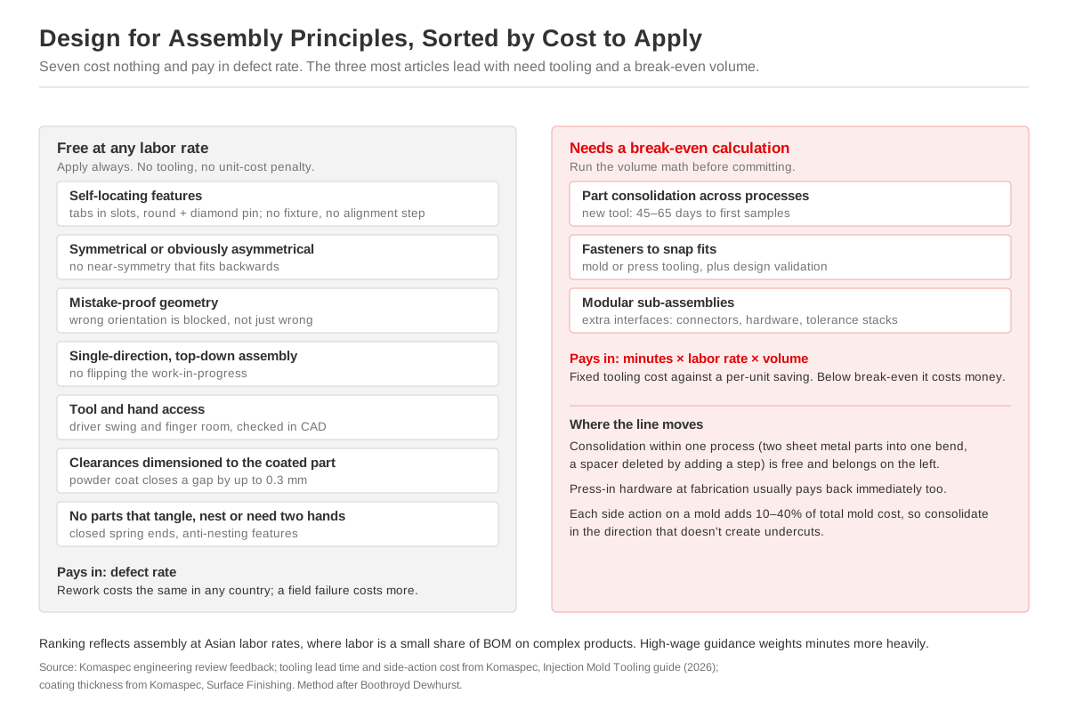
Other than the time it takes to adjust the drawing, applying these principles comes at absolutely no cost. They should be applied to every design before it is sent for production.
1. Design Parts So They Locate Themselves
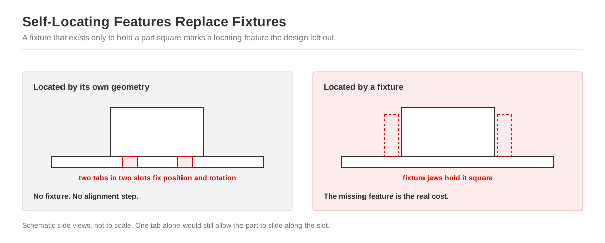
If a part can hold itself in position because of its geometry, the operator won’t need to align it or use a fixture to ensure it’s in the right spot. For example, this can be accomplished with tabs that go into slots, a seating face with a round and a diamond pin, or a boss that goes into a counterbore.
At this stage, these geometries are still a feature of your drawing, but they should be tested physically. Get the list of fixtures for one of your existing products and sort those fixtures into two groups.
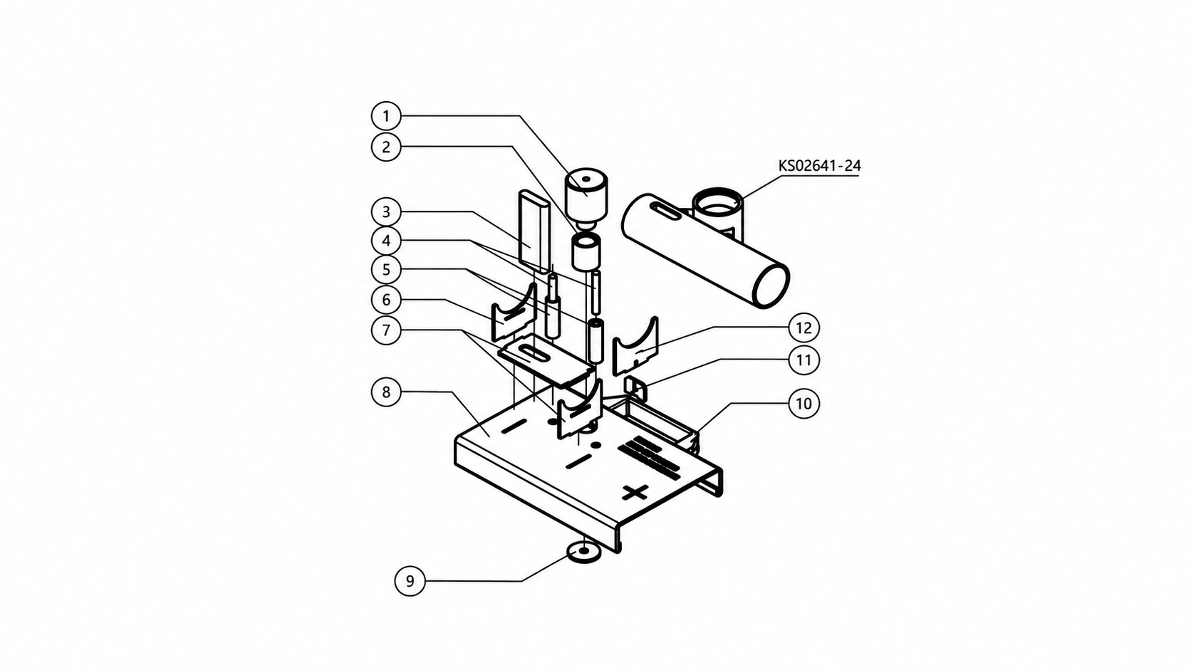
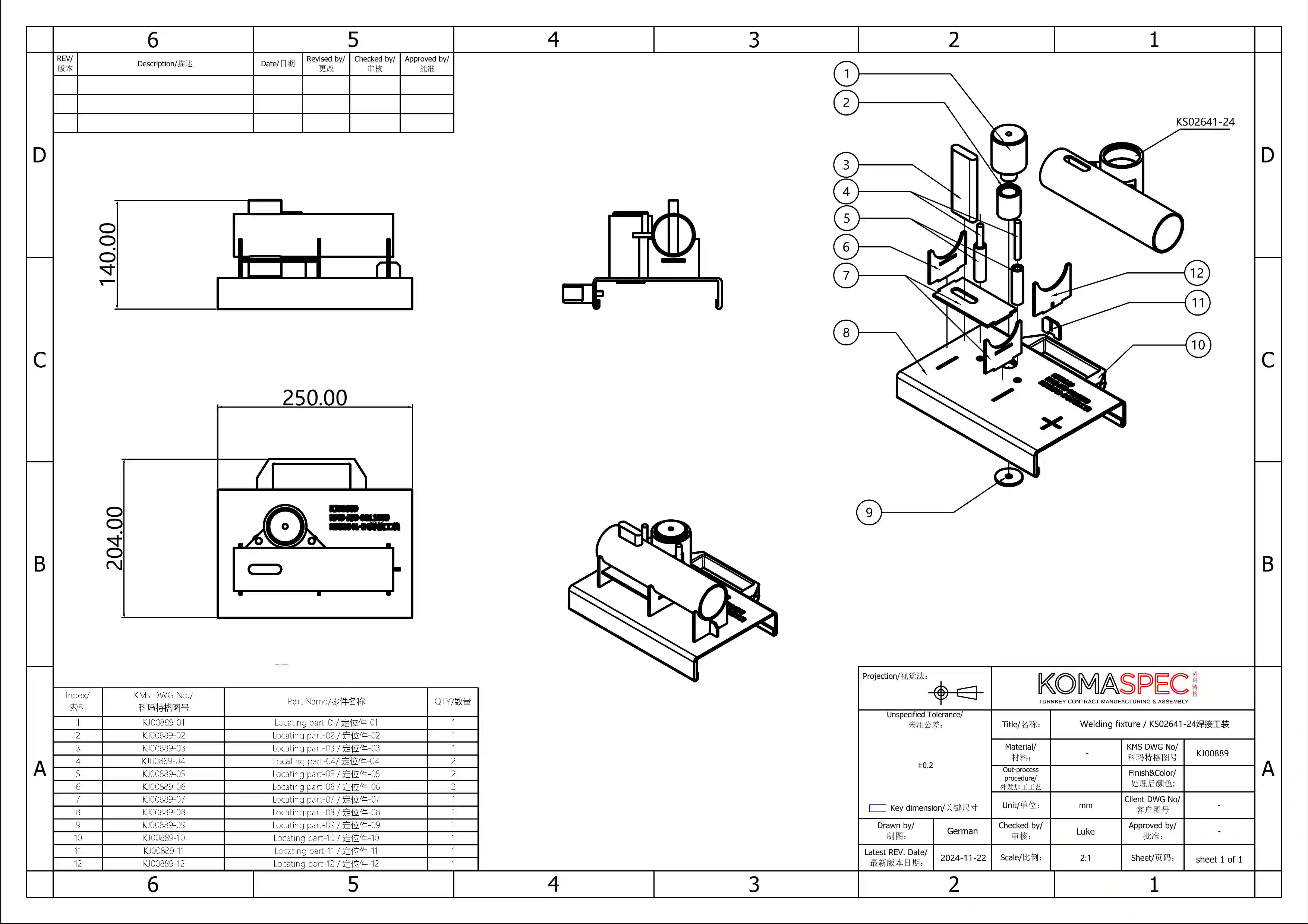
First, the joining fixtures. The need for these is not an assembly issue. For instance, a welding jig is meant to hold separate parts while heat distorts them (ours hold 8 to 13 machined locating parts because those parts are small and irregular). You can’t eliminate the need for that by changing a part’s geometry. So that will stay.
2. Make Parts Symmetrical (Or Make Them Obviously Asymmetrical)
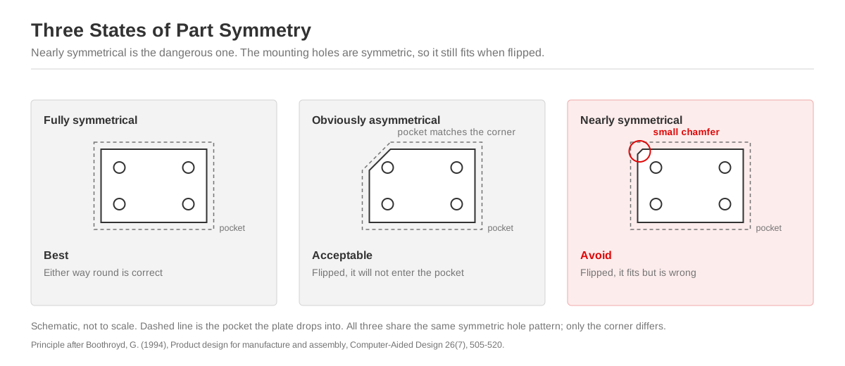
Assembling a fully symmetrical part is ideal, because it’s easy to get the orientation right.
The next best option is a part that’s obviously asymmetrical, because the operator can tell at a glance that the orientation is correct (rather than carefully inspecting each part after it has been installed).
What you want to avoid are parts that look almost symmetrical, but aren’t. That’s how you end up with a part that gets put in backwards without anyone noticing until the assembly is complete.
3. Make It Impossible to Assemble the Parts Incorrectly
Even the best operators can mess up a step. Poka-yoke geometry makes it impossible. A mounting hole moved deliberately off the symmetry line, a keyed connector, a notch on one corner, a boss that fouls the housing if the PCB goes in flipped — each of these blocks the wrong orientation outright, so a slip-up can’t make it into the finished assembly.
Of all the principles in this list, this is the one that delivers the highest value for the least effort. Fool-proofing features cost practically nothing on a laser-cut or molded part, and they’ll save you the costs and delays caused by improper assembly.
This is sometimes derided as “designing for incompetence.” That’s the wrong attitude. Even seasoned and skilled operators are prone to errors when connecting hundreds of units per shift. This simply takes that pressure and burden off their shoulders.
4. Assemble from Top Down
Any time a part has to be reoriented during assembly, it costs time and introduces a risk that it will be improperly aligned. To avoid this, stick to a single orientation (as much as possible). Ideally, you would start with a base part that sits in the fixture once, and every other component would be stacked downward onto it.
5. Design for Access
Meeting the clearance for the part doesn’t mean it’s easy for the operator to access it. If you’ve got a screw in a recessed pocket, you need to factor in the space needed for it to be fastened comfortably (i.e., the length required for driver engagement, along with sufficient room for the swing radius). Likewise, a connector is only practical if there’s enough space for fingers to reach in and seat / unseat it.
Use an actual driver model (not a cylinder) to check for tool access in CAD.
6. Dimension Clearances Based on the Finished Part, Not Its Bare Surface
Many designs base clearances on the dimensions of the bare metal part. But once that part gets coated, those numbers change.
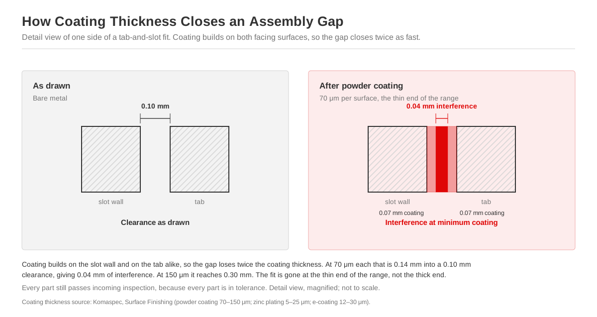
Powder coating adds anywhere from 70 to 150 μm per surface. So if your assembly has two coated faces that will be joined together, there could be up to 0.3 mm of added thickness between them. And a coated hole will also lose twice its coating thickness on diameter.
If your part is taking zinc (5–25 μm) or e-coating (12–30 μm), its dimensions won’t change as significantly. But they will change, and it could make the difference between meeting clearances and exceeding them.
If this isn’t fixed in the drawing, it usually needs to be dealt with on the production floor. So if you designed a tab that won’t meet clearance after the part is coated, someone has to take the time to manually file it down for every single unit.
Here are a few simple things you can do to prevent this:
- Include coating allowances in the part’s dimensions so it’s precise and accounted for (not just waved away with a note that says “allow for finish”).
- Mask features that have to remain bare, like ground paths, bearing bores, slip-fit faces, and threads. But masking adds cost for every part, so use it sparingly.
- Install self-clinching hardware before the coating is applied, and specify whether threads get chased afterwards.
This problem only gets uncovered late in the assembly stage. That’s because every part will be within its tolerance range and will pass the incoming inspection. It’s only once everything has been coated and operators are struggling to assemble parts that the issue becomes obvious.
7. Avoid Parts That Tangle, Nest, or Need Two Hands for Installation
These parts mean extra handling time for each unit. A design with open-coil springs, stampings with hook features, and thin flexible clips slows down assembly on every unit. Opting instead for closed-and-ground spring ends or stampings with anti-nesting features adds some process time at the front end, but it shaves assembly time off every single unit you build.
The DFA Principles That Are Only Worth Implementing Sometimes
These next three are the ones most DFA articles lead with. They can deliver the largest savings, but each one carries a cost of its own, so they’re only worth applying once you’ve run the numbers for your volume.
8. Part Consolidation
Combining parts can be tempting, especially when you see the results certain companies have enjoyed. For example, IDEXX reduced the part count for a veterinary device from 183 to 31 and got rid of all 63 fasteners from the initial design, resulting in an assembly time that dropped from 45 minutes to just 11. Similarly, a vehicle front support structure built by BAIC was optimized from 35 parts down to 12 by integrating six metal stampings into a single plastic part, resulting in 30% lower cost and 24% reduced weight.
Those are impressive results. But in the case of BAIC, consolidating stampings into one molded part is something that can only be done using an injection tool. And that means investing capital, dealing with a lead time of roughly 45 to 65 days to first samples, and a fixed cost that only pays itself off once you reach a significant production volume. For BAIC, that was probably the right move. But for smaller production runs, it would be a hefty tooling bill that would be difficult to justify.
That being said, consolidation is almost always the right move when it doesn’t cost you anything. If you can merge two sheet metal parts into one bend, move a boss to an existing molded part, or get rid of a spacer by adding a step to the part below it, those are changes that will pay for themselves at very low volumes. But if you’re looking at a change in process or tooling to make the consolidation happen, do the calculation to confirm whether it would actually translate into savings.

9. Replacing Fasteners with Snap Fits or Integrated Features
Eliminating as many fasteners from your design as you can is also appealing because it’s a small change with a big effect. Each fastener you delete from the drawing will cut several insertion operations out of the assembly.
Snap fits, on the other hand, add no cost per unit. But there are constraints to adding them: 1) snaps that release for service have to be designed for release, and 2) molded snaps need a tool and sheet metal snaps need press tooling or added forming. This isn’t worthwhile at lower volumes, so swapping out fasteners with snap fits isn’t automatically a better choice.
For sheet metal, the right strategy is often to move fasteners upstream and use fewer varieties. Press in the self-clinching studs, standoffs, and nuts at the fabrication stage so it all happens once on a machine instead of having to be done one-by-one during assembly. And reducing the number of fastener types will have a bigger impact than reducing the total fastener count. Why? Because every individual type of screw will add a separate bin to the workbench, require its own driver setting, and add another point of failure (i.e., the operator grabbing a screw from the wrong bin).
For advice on this selection process, check out our guide to designing sheet metal parts to accommodate hardware.
10. Modular Sub-Assemblies
Using sub-assemblies means those parts can be built and tested off the main line. This helps keep your timeline more manageable, but each sub-assembly also means extra interfaces, connectors, and fasteners, plus a tolerance stack.
Modular sub-assemblies make sense when you have several design variants that all share modules, or if the sub-assembly will need its own functional test before the final build.
But if you’ve got a product without any variants, a sub-assembly usually just adds extra parts.
How Volume and Assembly Location Factor into DFA
The DFA Index measures assembly in terms of seconds. How much each of those seconds will cost you depends on the labor rate where your product is assembled.
So, is it cheaper to get your product built in China or in Vietnam?
We ran this question by our engineers. They told us that rates for skilled manufacturing are about 45% lower in Vietnam. But if you take productivity into account, the real difference is closer to 25 or 30%. For skilled work, the difference is even smaller. In Vietnam, welders and solderers are in short supply and command rates close to those in China.
Another consideration is that Vietnamese workers generally won’t take overtime. So peak demand doesn’t mean pushing work hours. Instead, it means running a second shift at higher rates.
On top of that, there are regional differences. The wages in Guangdong are well above those in Chongqing, so even within China there is variability.
So, what does this mean for DFA? A 25% or even a 30% reduction in labor rate might not translate to a significant cost reduction for every design change. Remember, the goal of DFA is to trim seconds from a unit’s assembly time. At lower volumes, those savings might barely register, and consolidating parts just to save on assembly time could potentially end up costing you more.
Being overly focused on labor rates could also backfire. If you’re building a complex electromechanical product, the assembly labor is only a small portion of the cost. The majority of it comes from materials and components, and these are often more expensive in Vietnam than in China. If your product is footwear, textiles, or woven furniture, then the cost of labor will be one of your main concerns. But if your build is a sheet metal enclosure that houses several purchased components, then volume and tooling are going to matter more than hourly rates.
The DFA principles you can apply for free will lower cost by reducing the rate of defects, not by speeding up assembly. And the rework to fix a part that was installed backwards is going to cost you the same no matter where your assembler is located (and a field failure will carry its own costs that have nothing to do with labor rates).
Most DFA guidelines you’ll come across are written under the assumption that you’re applying these principles to high-wage assembly. But when working with facilities in lower-wage regions, assembly time is generally less important than reducing error rates.
When DFA and DFM Give Opposite Recommendations
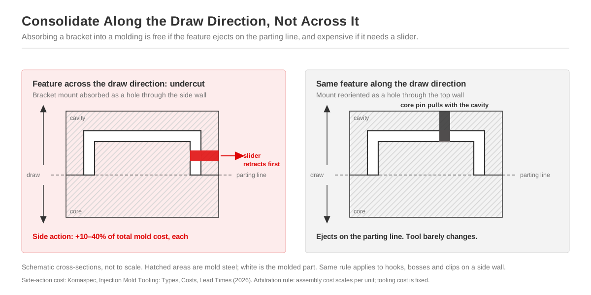
Optimizing a design for assembly can sometimes make it worse from a manufacturing standpoint. This is most obvious when it comes to molding, because consolidating parts usually means absorbing features that used to be separate brackets. Those features then arrive as undercuts, which require a side action or a lifter. And each slider mechanism carries 10% to 40% of total mold cost.
So, how do you balance conflicting recommendations from these two approaches?
Our approach is to see assembly as a cost that is driven by labor, and it scales with every unit, while complexity cost is mainly driven by tooling and is fixed for the entire production run.
This means if you’re producing less than a few thousand units annually, a slightly worse assembly built from simpler parts is generally going to be preferable. So if you can merge features without changing the tool or swapping in more complex parts, that’s probably worthwhile. But if consolidating parts means you’ll need a slider, that’s a cost that might not pay for itself until you hit more significant volumes.
How to Run a DFA Review on Your Own Design
Follow these steps (in order):
- Count every part used to assemble the product, including all fasteners.
- Subject each part to the three-question test, asking whether it will move during the product’s operation, must be made of a different material, or needs to be easily removable for servicing or assembly.
- Score your current design using the DFA Index. This will give you a baseline to compare against later revisions.
- Evaluate candidates for consolidation. Parts that can be consolidated without cost can be dealt with now. If consolidating would require tooling or other potential expenses, run the numbers to see whether it would result in a genuine cost reduction.
- Assess whether each fixture is needed. If your design relies on a fixture whose only job is holding a part in the right position, it can probably be replaced by swapping in a part with locating features.
- Identify every step in the assembly that involves reorientation. Every flip is added time and should be eliminated unless it’s unavoidable.
- Get rid of any parts that are nearly symmetrical. Reduce assembly errors by replacing them with parts that are either fully symmetrical or obviously asymmetrical.
- Confirm that every mating clearance will be met after the finish has been applied, instead of relying on the numbers for bare material.
If you run through these steps before the tooling is set, it could make your product far easier to assemble. CNH did this with their tractor cooling package while still at the concept stage and it cut their part count down from 352 to 294, resulting in an 18% reduction in assembly minutes.
Doing this once is a step in the right direction. Doing it multiple times is better. That’s why our engineering team provides feedback at three separate stages. First at RFQ (for architecture and part count), then at the drawing stage (to check tolerances, fasteners, and access) and once more at the sample build. After that, it still goes through a pilot run (between 20 and 100 units) to see whether the jigs, cycle times, and assembly sequence actually hold up on the production line. The handling problems that no CAD model will reveal tend to surface somewhere in those first 20 units, so it’s worth running before the full order gets rolling.
Need a second set of eyes on your design? Our engineers review customer designs before quoting. That way, you know exactly where the break-even point is for tooling investment. And if your product will be a populated enclosure, our box build design guide covers the decision-making process on that front.
Frequently Asked Questions
What is DFA (design for assembly)?
It is a method for evaluating and revising product designs so they are optimized for assembly. The goal is to create new iterations of the design that reduce assembly time, cut down costs, and reduce error rates. It is mainly concerned with reducing the number of parts (where possible) and ensuring that each part can be handled and installed with ease.
What is the difference between DFM and DFMA?
Design for Manufacturing (DFM) reviews and revises designs to ensure that they can be produced economically and meet all required tolerances. Design for Manufacturing and Assembly (DFMA) combines the principles of DFM with those of DFA to ensure that the product can be fabricated and put together efficiently and with minimal errors.
What are the main design for assembly principles?
Some cost nothing to apply and belong in every design: adding self-locating features, ensuring that parts are symmetrical (or obviously asymmetrical), sequencing assembly so it runs in one single direction, using parts with fool-proof geometry, eliminating parts that tangle, ensuring that all connectors are easily accessible, and measuring clearances based on the coated part (not the bare material). Other principles only pay back at higher volumes or on specific types of production runs, including consolidating parts, snap-fits, and using modular sub-assemblies.
How do you calculate assembly efficiency?
Use the DFA Index. This is a formula that takes the theoretical minimum part count for your design, multiplies it by three seconds (the ideal assembly time for each part), then divides it by the total assembly time. Use the result as your baseline to measure whether design revisions are moving in the right direction.
Does surface finishing affect assembly clearances?
Yes. Surface finish adds additional thickness to the material. Powder coating adds 70–150 μm on each surface to which it’s applied. That means two coated mating faces can lose up to 0.3 mm of clearance. Clearances and tolerances should always be measured on the finished part, not the dimensions of the bare material.
When should design for assembly start?
Very early, at concept stage. Once the architecture is fixed and the tooling is cut, DFA revisions become more complicated and costly. But to ensure a fully optimized design, it is still worth running through the DFA process again at the drawing stage, then once more after sample build.