A Guide to Box Build Design
- Introduction
- Key Takeaways
- What is Box Build Design?
- Choosing the Right Enclosure for a Box Build Assembly
- Integrating Components
- Common Performance and Reliability Design Considerations
- Important Manufacturing Considerations
- Summary
Introduction
Box build assembly design is a challenging, specialist area of manufacturing.
Box build assemblies are complex, compact units that have to meet a wide range of dimensional and mechanical requirements. They often need to operate sealed with significant amounts of heat output internally, while they need to resist corrosion, wind, snow, rain, external EMI, etc.. The design needs to consider space limitations, heat output, cooling, EMC, assembly, service, and a whole range of requirements.
In this article, we’ll introduce the basics of how to approach box build design and develop a manufacturable and useful assembly.
Key Takeaways
- Box builds require a measured approach to design – thing through enclosure, component and assembly requirements based on the end needs
- There often needs to be an iterative approach – designing, reviewing, redesigning, testing, retesting, etc. to be able to have a really effective design.
- There needs to be a combination of DFM and DFA advice to simplify production and service - having a manufacturer who understands design for manufacturability can save you a lot of heartache and wasted time.
- Prototyping and testing are crucial – how the product will perform in field conditions can’t always be anticipated during the design phase.
Table of Contents
What is Box Build Design?
Box build design is an aspect of product design focused on electrical assemblies where the components are fully integrated into a standalone enclosure (box). This design includes not only the assembly and enclosure, but the specification and review of the full product performance, including components such as printed circuit boards, cables, mounting hardware and other electronic, electrical and mechanical components.
Many of the challenges that arise in aspects such as enclosure design, component selection, system layout and integration and cable system design are unique to box build assemblies and require specialist knowledge.
Box build assemblies are different to printed circuit board assemblies (PCBAs). PCBAs are circuit boards with components mounted onto them that are not integrated into their final system. Once manufactured, a box build assembly is ready for use. A box build assembly can either be a finished product itself or it can be integrated into a finished product.
In industry, box build assembly is often referred to as ‘system integration’.
Choosing the Right Enclosure for a Box Build Assembly
The enclosure (box) is the most visible component of a box build assembly.
What’s not always immediately apparent, however, is the number of functions the enclosure performs.
Most enclosures need to:
- protect internal components from physical damage
- provide weather or waterproofing
- provide structural support
- allow for internal mounting as well as mounting onto other surfaces
- facilitate connectivity with other components
Some enclosures may also need to provide other functions such as thermal protection, passive cooling or electromagnetic shielding.
Custom vs Off-the-Shelf Enclosures
Custom enclosures
These are very useful when there are unique requirements for a box build assembly.
- If the unit needs to be shaped to be integrated with other units, for example, a custom enclosure can be made to the exact dimensions.
- Otherwise, there might be other unique requirements, such as for shock or vibration protection, or there might be branding requirements.
- The more demanding the application, generally the greater the need to specify a custom enclosure.
- It is also possible to purchase a standard enclosure and modify via machining or other methods to meet exact needs.
Off-the-shelf enclosures
These are available in a huge range of types, and it’s often possible to find an enclosure that fits a given project.
- Units that are built to standardized sizes often integrate with other components.
- Off-the-shelf boxes are also often manufactured in line with certification requirements such as NEMA or UL, which simplifies certification.
- They are also generally lower cost and have lower MOQ requirements.
Dimensions, Mechanical Compatibility and In-Use Performance
It is crucial to accurately assess what requirements an enclosure must conform to at the design stage. Generally the requirements are dimensional, mechanical, assembly, connectivity specifications, market needs and performance.
Some of the most important factors are the following:
Assembly Considerations
- Accessibility and serviceability
- Component fit and internal layout
- Cable management and routing
- Mounting and integration
Mechanical
- Mechanical strength and durability
Material selection & finishing
- Injected, thermoformed or machined plastics
- Sheet metal or machined metal
- UV, weather-resistant, or corrosion resistant coatings
User interface and controls
- Membrane switches
- Touch screens
- Physical buttons
Performance
- EMI/RFI shielding
- Thermal management
- Environmental protection
Market Considerations
- Compliance and safety
- Manufacturability and cost
- Aesthetics and branding
Material Selection
Material selection is the basis of box build assembly enclosure design.
The material should be selected based on the product’s intended use and environment. The most important factors are generally:
- mechanical strength
- thermal conductivity
- electrical properties
- environmental resistance
- weight
- manufacturability
- cost
- aesthetics
- compliance and safety standards
- EMI/RFI shielding.
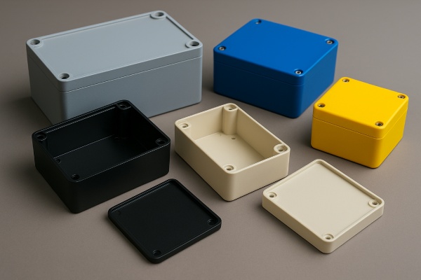
Plastic Enclosures
Plastic box build enclosures have physical properties that are advantageous in certain use cases, such as their lighter weight, corrosion resistance and ease of waterproofing. On the other hand, they are less effective in other situations. They’re less resistant to impact and abrasion, and they have lower resistance to UV light in outdoor use, for example.
One big advantage with plastic is that it is easier to make complex shaped enclosures.
Plastic enclosures often require specialist tooling to manufacture, though this can vary from inexpensive (thermoforming or vacuum casting) to very expensive (plastic injection). This can create higher upfront costs and add to lead times. Because of the tooling amortization and relatively high set-up costs, plastic is not economic for small production orders but is very cost-effective for larger Volumes.
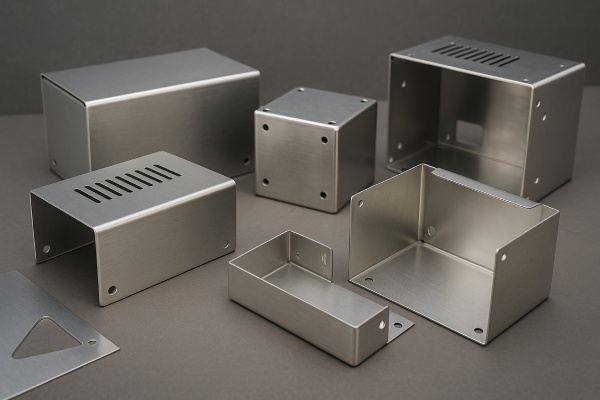
Metal Enclosures (Sheet Metal)
Metal enclosures, typically made from sheet metal or diecast aluminum, are physically stronger and have greater impact and abrasion resistance. They can also be manufactured to a wide variety of shapes through processes such as stamping, laser cutting and sheet metal bending. They also have other beneficial properties, including electrical conductivity and EMI shielding properties.
If done via laser cutting and bending, there is little to no need for product-specific tooling, making it very inexpensive for small batches. Stamping will require tooling investment, but it is often significantly cheaper for small products compared to injection tools.
Part costs will be higher when tooling is taken out of the equation, which means sheet metal enclosures are usually used for low to medium volumes (dozens to the low thousands).
Disadvantages can be higher materials cost, vulnerability to corrosion and higher weight. Metal box build enclosures are also more limited in terms of size, shape and configurability. There can be other drawbacks, such as difficulty waterproofing them.
Metal vs Plastic Box Build Assembly Enclosures
The physical properties of plastic and metal are usually the first consideration when making a choice for a box build assembly.
Here’s a comparison of the two materials:
| Advantages | Disadvantages | |
|---|---|---|
| Plastic |
|
|
| Metal |
|
|
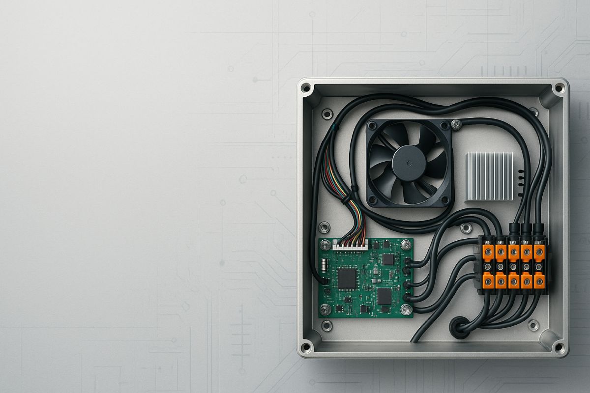
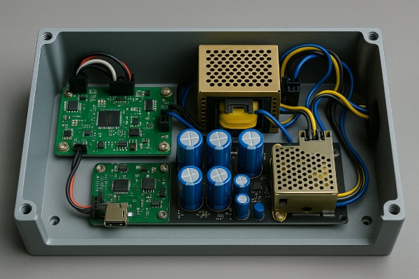
Integrating Components
Component integration requires very careful planning in box build assembly design. All components in an assembly need to fit together, function as intended and allow for maintenance. They also must not interfere with each other and must allow for heat management. There may be other considerations, such as maintaining signal integrity in transmission components.
Component Selection
Some of the most common components are:
- Printed circuit boards
- Cables, wire harnesses, connectors and terminals
- Switches, buttons, indicators and displays
- Sensors and actuators
- Cooling elements (fans, heatsinks, vents)
- Power supplies
- Mounting hardware, enclosure panels and housings
- EMI/RFI shielding materials
- Gaskets and seals
At the component selection stage, a designer should take into account the electrical, mechanical, and thermal compatibility of all the components. Parts need to be compatible, space constraints need to be managed, parts need to be integrated for reliable performance, and durability needs to be ensured. Often, regulatory requirements also need to be met.
Designers should also take production cost and manufacturability into account.
Some good design best practices to follow are:
- Use standard components when possible: Opt for common, off-the-shelf parts rather than custom components where feasible to aid procurement and quality.
- Review the bill of materials and design out soon-to-be obsolete parts to avoid procurement difficulty.
- In case the product needs to be certified, defer to pre-certified components (rUL, CE, etc.) wherever possible to simplify the process
Key Considerations for Internal Component Layout
In this section, we’ll look at three of the most important things to consider when it comes to component layout.
1. PCB Placement and Mounting
PCBA placement is an important initial consideration in box build assembly design. The placement of the PCBA affects thermal management, signal integrity, mechanical stability, ease of assembly, cable routing and accessibility for testing or maintenance.
Good PCBA positioning:
- Stabilizes the PCB and allows for reliable connectivity.
- Allows for managing flex and vibration concerns.
- The PCBA should be easily accessible for mounting and dismounting, as well as testing (by jig or fixture) if needed
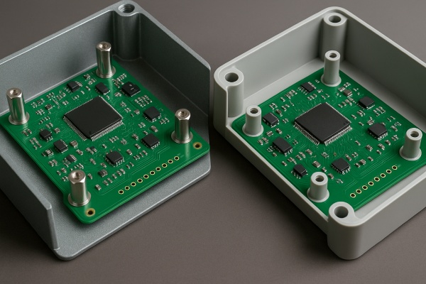
PCBA mounting
- Metal enclosures - Standoffs (hyperlink), which are essentially long posts are a standard choice to mount PCBAs as they isolate it mechanically and electrically from the surface of the enclosure
- Plastic enclosures – molded in screw posts are often the best approach as this is a low-cost, simple way to mount the PCBA.
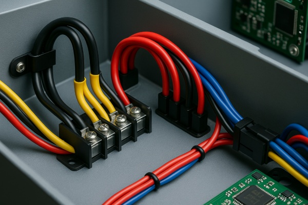
2. Cable Management
Cable management can be challenging in box build assemblies. Cables need to be routed so they do not interfere with each other or with components in the assembly. Ease of assembly and maintenance access are also important.
Cable Management Tips
- Default to riveted or screwed cable routing brackets or mounts – they are much less likely to fail than something stuck on using 3M adhesive, especially in a hot environment
- The bend radii in wires and cables need to be minimized as much as possible to prevent damage to harnesses and to relieve strain on connectors
- It’s important to consider connector type and reliability, especially when a cable is bent – a locked in connector will be secure and generally provide more assurance against being knocked out
- In cases where there are simply too many cables or harnesses to easily manage, you can consider adding a terminal block or relay as an easily accessed service point.
3. Thermal Management:
It is important to identify heat-generating components when designing a box build assembly and to design for thermal management.
The key factors that influence thermal management are:
- Material selection
- Component layout (spacing of heat-generating components)
- The environment the box build will be used in
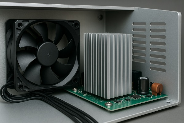
When considering how to manage heat dissipation in a product, there are two primary approaches:
1. Active Cooling
Using fans or electrical components to “actively” manage the heat in the enclosure.
- This usually means more expense and complexity, but has the ability to dissipate much more heat more rapidly
- Electrical fans, compressors, Peltier cooling, pumps, etc. are the typical means of cooling.
2. Passive Cooling
This uses the design of the enclosure itself, the material (often aluminum), heat sinks or vents to dissipate heat.
- This is generally a simpler and more cost efficient method, but it cannot move too much heat too rapidly.
- Aluminum heat sinks or plates, or the enclosure itself can be an active cooling method. Often, the components which generate the most heat will be mounted directly on the enclosure just for this reason.
- Vents in the enclosure or internal heat barriers can also help to manage heat and protect more fragile components.
Common Performance and Reliability Design Considerations
Three performance considerations that often come up in box build design are EMI/EMC shielding, waterproofing and environmental protection and shock and vibration resistance.
- EMI/EMC shielding – this relates to preventing electromagnetic signals from interfering with internal components and to ensuring the box build assembly does not emit electromagnetic signals that affect other devices. Where this is an issue, enclosures should be designed to block, absorb, or redirect electromagnetic waves.
- Waterproofing and environmental protection – Water, dust, dirt and other environmental contaminants often need to be prevented in box build design. Gaskets, O-rings, sealants and carefully designed enclosure joints are all used to manage these factors. Waterproofing can be a major challenge in box build design.
- Shock and vibration resistance – Box build assemblies that need to withstand shock and vibration should be built with features and materials that safeguard internal components. This can include shock-absorbing mounts, cushioning materials (e.g. foam or rubber), rigid structural support or secure fasteners.
Important Manufacturing Considerations
Optimizing Design for Manufacturability (DFM)
Design for manufacturability (DFM) is the process of designing products and components so they are easy and cost effective to manufacture. Good designers often make time and financial savings through designs that understand manufacturing processes.
In box build assembly design, taking opportunities to minimize enclosure complexity (modular designs often help), standardize components and optimize designs for assembly tools. Other steps are reducing the number of fasteners and custom parts, standardizing cable routing, allowing for tolerance stack ups and facilitating access for testing and inspection during manufacture.
We can provide you with DFM advice for your box build assembly at Komaspec.
Prototyping and Testing Box Build Assembly Designs
Box build assemblies need to be prototyped and quality control tested to ensure proper dimensioning, performance, and regulatory compliance. It’s important to identify problems early to avoid costly redesigns or failures.
Prototyping
Prototyping normally involves creating a functional mock-up using 3D-printed, machined, or fabricated enclosures along with internal components. Prototypes are tested for correct dimensions, thermal performance, structural integrity, and ease of assembly.
Prototypes don’t need absolute fidelity (they don’t need to completely match) the final product – you can make compromises in fabrication, mounting or certain material aspects to simplify and speed up the prototyping process. Substituting laser cut sheet metal for stamping, or 3D printed parts is a common approach.
Ideally, start with fast and dirty prototypes to think through the basic design / assembly approach, then move to more complex and higher fidelity prototypes as you move towards mass production.

Quality Control & Testing
Box build assemblies are normally tested at various stages during manufacture. Typically, there is a stage of initial functional testing and in-process quality checks during manufacture. After box builds are assembled, there are normally final system-level tests to verify performance, safety, and compliance.
The main testing methods in box build assembly include:
- Visual inspection – to check for obvious defects, missing components, and workmanship.
- Functional testing – to confirm correct operation of electrical and mechanical systems.
- Continuity testing – to ensure that all circuits and connections are properly established.
- Hipot (high potential) testing – to verify insulation resistance and identify any leakage paths that could lead to electrical failure or safety hazards.
- Ground continuity testing – to confirm that all conductive parts are properly grounded and meet safety standards.
- Environmental stress testing – such as drop tests, vibration, humidity, or temperature cycling to simulate real-world conditions.
- EMI/EMC compliance testing – to check for electromagnetic interference and compatibility with regulatory limits.
- Ingress Protection (IP) testing – to verify that enclosures meet specific resistance levels against dust and water intrusion (e.g. IP54, IP65, or IP67). These tests are critical for assemblies used in harsh or outdoor environments.
Standards often referenced during testing include IEC 61010, IEC 60529 (for IP ratings), UL 61010-1, and other CE/UL/CSA certifications depending on target market and application.
Summary
Box build assembly manufacturing is a specialist area of engineering. Expert design is required to ensure that all the interconnected components in a box build work correctly, work together and can withstand the environment they operate in. Oversights can lead to failure and costly rework or product replacement.
Good design can also save money and speed up production by identifying lower-cost and more efficient production methods. Careful prototyping and testing are also crucial components of a successful box build production run.
Komaspec is a Canadian-owned manufacturing company with over 20 years of experience across multiple manufacturing disciplines. With facilities in China, Vietnam, and Mexico, we provide a turnkey box build assembly manufacturing service and manage projects for clients across a wide range of industries.