- Introduction
- CAD Tools and Sheet Metal Part/Product Design
- CAD Vs Traditional Design
- Factors to Consider When Choosing CAD Software
- Comparison of Popular CAD Software Brands
- A Note on Designer Availability
- Komaspec
- FAQs
Which CAD Software Is Right for Your Sheet Metal Project
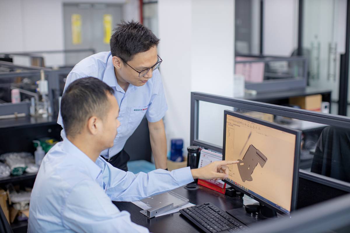
Table of Contents
Introduction
Good product design is fundamental to the success of companies that sell sheet metal fabricated products. The product design process takes an original concept and turns it into a physical product that manufacturers can create. A lot depends on design.
CAD tools can be used to improve the design of sheet metal fabricated products.
Using CAD tools to improve designs has advantages both during the process of manufacturing and after. Good design makes manufacturing easier, faster and more economical, and it also results in more successful products.
If you aren’t already using CAD software, you may want to talk to your fabricator to see if they have a recommendation for you.
If you’d like to talk to Komaspec about your choice of CAD tools – Contact Us.
CAD Tools and Sheet Metal Part/Product Design
Design affects the performance of a product and its manufacturability.
In the performance of a product, design can be looked at as affecting two essential elements: form and function. CAD tools help with the analysis of both areas. CAD tools can be used to both visualize a final product and test its performance and usability.
Good CAD software for sheet metal product design and manufacturing will help you understand your product’s:
- Material properties.
- Structure and mechanics.
- Form and usability.
- Performance and user safety levels.
The best CAD software will also help you:
- Optimize your design for manufacturing.
Complete and comprehensive product design drafting software also includes tools to reduce wasted resources during manufacturing, minimize the need for physical prototypes and achieve other objectives.
CAD Vs Traditional Design
With CAD software, all stages of the design process can be handled through a digital design system. This compares to more traditional design processes that may require stages such as sketching, modelling, rendering or prototyping. CAD software is designed to be inclusive of these phases but through a much more simplified process.
Comprehensive all-in-one CAD software will also have the capacity to take your product from start to finish without relying on exporting or importing files into other programs.

Fig. 1: Sheet Metal Manufacturing Design Review at Komaspec
Factors to Consider When Choosing CAD Software
In this section, we’ll look at the main things you should consider when choosing design software for sheet metal fabrication.
Or instead, skip ahead to our sheet metal product CAD software comparison table.
1. Product Performance Analysis Capacity
Having product performance analysis capabilities in CAD software gives the designer the ability to assess the safety and physical integrity of a product before it reaches the prototyping or manufacturing stages.
Using software, the designer can simulate different stresses on their product. These commonly include static, kinetic or thermodynamic stresses.
Having this capability in CAD software helps to eliminate the need for expensive physical iterations of a product and can identify safety or feasibility concerns earlier than with other design processes.
2. Design for Manufacturability Capability (DFM)
With design for manufacturability (DFM) capability, CAD software will validate the ability to manufacture a part efficiently. Making this analysis in the early design phases with CAD software allows changes to be made before issues are found on the production line.
DFM capabilities can be advanced. It’s possible for CAD software to identify issues with tolerances, identify ways to minimize processing, factor in assembly and find other ways to manufacture a product more efficiently. Taking a DFM approach can lower your cost of manufacturing and provide better, clearer directions for the fabricator.Note that most of the software products reviewed in the table below on this page provide a very similar set of features when it comes to designing for manufacturability.
Find out more about DFM and the importance of design precision in this Komaspec article.
3. Cloud Version
Cloud storage has caused a widespread change in the way people interact with data, and this is no different with software used in industrial applications.
Beyond storing your files safely and securely and reducing the need for redundancies in physical data storage, cloud storage has made data sharing easier than ever before. During product design and manufacturing, where multiple parties may be involved at both stages, being able to easily share data can make things much easier.
CAD software with cloud capabilities allows for real-time collaboration with your design colleagues and with your manufacturers. It can allow designers to quickly share alternative or updated designs, and during manufacturing, it can allow designers and manufacturers to collaborate much more easily.
Some cloud-based CAD software also reduces the computational load on the users’ CPU by offloading computing functions to the cloud processor. CAD software has a significant computational load, and being able to offload this to a third party can be advantageous.
4. Compatibility
If you’re using other engineering or design software for things like simulations or virtual reality (VR), you want to be sure there is interoperability between all your different tools, so you can use them all to their fullest ability.
You also want to consider that software will evolve in the future, and you’ll want a solution that will remain compatible as you move forward.
Finding CAD software that is compatible with the other systems you’re running will simplify things and mean there’s a shorter learning curve when integrating new software. The need for training among staff may be avoided as well.
5. Drawing File Formats
Not all drawing file formats are readable and useable by all systems. In fact, where they’re incompatible, features can be lost in transitioning from one system to another.
As such, it’s important to know the format requirements of others involved in the design and fabrication process and to choose CAD software that accommodates everyone’s requirements. Common formats include PDF, DWG, DXF (read more about DXF files for laser cutting here), STEP, IGES, Parasolid, STL, VRML, X3D and COLLADA.
Creating design file standards with your fabricator is a good idea if you’re doing more than just a one-off fabrication.
Another thing to keep in mind is that sheet metal begins as 2D and is formed into a 3D shape. A lot of engineering design today is done in 3D, and this doesn’t typically provide the dimensions, tolerances and other specifications needed in the sheet metal fabrication process. While modeling a design in 3D is a good approach, generally a 2D or print version is required to provide the tolerancing and specification information required for fabrication.
Note that there’s a move towards model-based design (MBD) methods that give flexibility to include the sheet metal fabrication requirements, such as dimensions, assembly, tolerances, etc. in a 3D model. This eliminates the need to convert files to a separate format for the fabricator, however it is not universally adopted, so the standard is still to provide multiple file formats
SolidWorks is one CAD tool that offers this capability.
The Standard for the Exchange of Product Data (STEP)
STEP is a CAD file format used to share 3D models between different CAD systems. Having an ISO standard for file exchange helps the industry overcome issues with compatibility. By maintaining a cohesive design standard, errors in interpretation and implementation can be avoided entirely.
STEP includes many different phases of the CAD process and the industries it effects.
Adhering to an international standard is crucial when collaborating with designers outside of your company or when working with your fabrication partner.
6. Cost
When it comes to cost, the best thing is to find a balance between features available and cost.
Many types of CAD software on offer come with an array of features. While there may be an allure to software with numerous and advanced features, you only need CAD software that does what you need it to do. If you buy a piece of CAD software with features you don’t need, you may never use them.
Focus on finding a solution that gives you the ability to design the sheet metal products you need to design. Only consider additional features if they benefit other areas of your business.
Also keep in mind that most engineering and design software has high resource demands and usually can’t be run on a standard PC or laptop. You may require a higher-powered machine to run the software effectively. Advanced software will be more demanding.
Comparison of Popular CAD Software Brands
| Product performance analysis | Cloud version | Price | Compatibility / API to connect to other software | Available file formats | |
|---|---|---|---|---|---|
| Alibre Expert | Performance analysis tools are not native to the software, but there are available add-ons: | None available | $2,000-$2600 USD | Alibre Script | Multiple including: |
| 1. Finite Element Analysis | (one-time purchase, price is dependent on license type) | STEP | |||
| 2. CAM Analysis | +$400-$500 USD/year | SAT | |||
| 3. Motion Simulation and Analysis | (updates and support) | DWG | |||
| DXF | |||||
| Supported File Formats | |||||
| Fusion 360 | Includes a simulation space with tools for: | Available for storage and collaborative design. | $495/year | Yes | Multiple including: |
| 1. Static Stress | Users can work collaboratively between Inventor and Fusion 360 using the cloud functionality. | ($125/ year for a Team Participant license) | Fusion 360 API | STEP | |
| 2. Nonlinear Static Stress | SAT | ||||
| 3. Event Simulation | DWG | ||||
| 4. Modal Frequencies | DXF | ||||
| 5. Structural Buckling | |||||
| 6. Thermal Stress | |||||
| 7. Shape Optimization | |||||
| Autodesk Inventor | Performance analysis tools include: | Available for storage and collaborative design. | $1,985 /year | Yes | Multiple including: |
| 1. Cyclic Symmetry Analysis | Users can work collaboratively between Inventor and Fusion 360 using the cloud functionality. | iLogic and the Inventor API | IPT | ||
| 2. Assembly Optimization/Bolted Connections | IAM | ||||
| 3. Weldment Analysis | IDW | ||||
| 4. Wind Load Analysis | DWG | ||||
| 5. Fabrication Analysis | IPN | ||||
| 6. Sheet Metal Analysis | IDE | ||||
| 7. Motion Load Transfer Analysis | |||||
| 8. Modal Analysis | |||||
| 9. Finite Element Analysis | |||||
| Catia | Performance analysis tools include: | Cloud-based storage and collaboration | Pricing not listed. Quote from a company representative required. | Yes | Multiple including: |
| 1. Nonlinear Structural Analysis | |||||
| 2. Thermal Analysis | CAA-RADE | IGES | |||
| 3. Simiulia Rule Based Meshing | DXF | ||||
| 4. Generative Part Structural Analysis | DWG | ||||
| 5. Generative Assembly Structural Analysis | STEP | ||||
| 6. Generative Dynamic Response Analysis | STL | ||||
| 7. Catia-Elfini Structural Analysis | Supported File Formats | ||||
| 8. FEM Surface | |||||
| 9. FEM Solid | |||||
| Creo | Performance analysis tools include: | Cloud-based storage | Pricing not listed. Quote from a company representative required. | Yes |
Multiple including |
| 1. Finite Element Analysis | Creo API | STEP | |||
| 2. Static Analysis | DWG | ||||
| Structural Analysis | DXF | ||||
| Supported File Formats | |||||
| IronCAD | The Multiphysics Analysis Extension includes: | None | Pricing not listed. Quote from a company representative required. | Yes | Multiple including: |
| 1. Finite Element Analysis | IronCAD API | STEP | |||
| 2. Stress Analysis | IGES | ||||
| 3. Thermal Analysis | Parasolid | ||||
| 4. Electrostatic Analysis | DXF | ||||
| 5. Static/Steady State | Import Formats | ||||
| 6. Dynamic/Transient Response | Export Formats | ||||
| 7. Modal/Vibrational Modes | |||||
| 8. Instability Buckling | |||||
| Frequency Domain | |||||
| Solid Edge | Solid Edge Simulation includes: | Cloud-based storage and design sharing | Pricing not listed. | Yes |
Multiple including: |
| 1. Finite Element Analysis | Synchronous Technology API | STEP | |||
| 1. Finite Element Analysis | Synchronous Technology API | SAT | |||
| Computational Fluid Dynamics | SAT | ||||
| DWG | |||||
| DXF | |||||
| Import Formats | |||||
| Export Formats | |||||
| SOLIDWORKS | SOLIDWORKS simulation is an add-on product that includes: | Cloud-based storage and collaboration | Pricing not listed. Quote from a company representative required. | Yes |
Multiple including: |
| 1. Linear Static Simulation | SOLIDWORKS API | STEP | |||
| 2. Cyclic Loading | SAT | ||||
| 3. Finite Element Analysis | DWG | ||||
| DXF | |||||
| SOLIDWORKS File Types | |||||
| SOLIDWORKS Supported File Formats |
Table 1: Comparison of Popular CAD Software Brands
A Note on Designer Availability
With the considerable amount of CAD software available on the market, it’s unlikely that you’ll be able to find a designer that is well-versed in all of it. That said, it isn’t necessarily important to choose CAD software according to what designers you work with use.
Some types of software, like SolidWorks, Fusion 360 and Autodesk Inventor, are common, so it will be easy to find designers that are familiar with them. However, most software ecosystems rely on the same fundamentals of 2D and 3D design anyway. And while there is always a learning curve to any new piece of software, a designer that is versed in at least one CAD suite should be able to adapt to a new one.
Note that some types of software are niche, like Alibre Expert or Catia. These are more common with aerospace or automotive engineering, and it may be difficult and or expensive to find a designer who is familiar with these formats and able to help you.
The best idea is to have designers work in the format they are familiar with and then export to STEP or STP, one of the more universal and easily translatable formats.
 Fig. 2. Komacut's Instant Manufacturability Feedback on Design
Komaspec
Our team of engineers and technicians here at Komaspec have more than 20 years’ experience in sheet metal fabrication in China. They’ll be glad to review your product design together with you and provide detailed design for manufacturability feedback and analysis. This will help you to improve functionality, select the right fabrication processes and reduce manufacturing and tooling costs.
Komaspec is a China based sheet metal and plastics contract manufacturer
We can review your product design and help you select the fabrication process that best suits your product’s needs.
Frequently Asked Questions
What is the best CAD software for sheet metal product design?
There are many different types of CAD software that can be used for sheet metal product design. Different types of software come with different functionalities, at different prices and with different computational requirements.
There are some brands of CAD software that are in common use, like SolidWorks, Fusion 360 and Autodesk Inventor. It’s important to shop around, however, because the best CAD software for sheet metal product design is the software that meets a user’s requirements.
The key things to consider are:
- Product performance analysis capacity.
- Design for manufacturability capability.
- Cloud version availability.
- Compatibility with other software and systems.
- Drawing file formats.
How much does CAD software for sheet metal design cost?
CAD software is available in all price ranges.
Free CAD software for sheet metal product design is available. FreeCAD is an example of a free piece of CAD software. It is possible to achieve good results with free CAD software. Most people, however, will find that to work productively and to achieve the best results, they’ll need to pay for their CAD software. The more expensive types of software can cost several thousands of dollars per license.
What is FreeCAD, and can I use it for sheet metal product design?
FreeCAD is an open-source 3D CAD software suite that can be used for personal and professional design projects. It is possible to use FreeCAD for sheet metal product design through their external Sheet Metal workbench.
Check out FreeCAD.
What’s the best 3D software for sheet metal fabrication?
For 3D software to be used for sheet metal fabrication, the file format will normally need to be converted to 2D before it can be used in manufacturing. CAD software that allows files to be converted into 2D is best for sheet metal product design.
SolidWorks and AutoDesk are both examples of programs that allow 3D files to be converted into 2D.
Model-based design (MBD) methods that allow sheet metal fabrication requirements, such as dimensions, assembly, tolerances, etc., to be included in a 3D model are also a good choice.
While there’s advantages to each of those on the market, in general, SolidWorks is one of the most widely used versions, though it’s positioning is as a premium product (full feature suite) and the cost corresponds to that (high).