Preparing Technical Drawings for Your Sheet Metal Fabricator
- Introduction
- General Considerations
- General Tips for The Design Process
- Drawing Contents
- Drawing Formats
- Komaspec
- FAQs
Table of Contents
Introduction
Before the production of your sheet metal product begins, it’s important to make sure your designs are prepared correctly. Not only does the quality of your finished goods depend on your designs, but manufacturing processes are heavily impacted by them as well.
Accurate and comprehensive designs let the manufacturer know exactly how to manufacture a product and avoid costly and time-consuming errors or sub-standard products.
Good designs go further, however, and optimize the manufacturing process. By considering a manufacturer’s working processes, resources and equipment in design, it’s possible to have a more efficient overall production process.
In this article, we’ll discuss how you can make sure you create technically correct and more manufacturable sheet metal drawings.
General Considerations
The most important general considerations to make in design are precision in terms of product design and the need to design for manufacturability.
Design Precision
Design precision is often critical when it comes to manufacturing sheet metal fabricated parts. Errors of even a very small margin can result in parts or products that fail, can’t be assembled or just don’t live up to expectations.
It’s important to ensure complete accuracy in your designs before you submit them to be used in manufacturing. A simple error in something like the size or spacing of a hole can have a big impact on the final outcome. Even if errors can be identified during production, they cause delays and unnecessary costs which can be avoided.
- Tolerances - As well as designs needing to be accurate, the level of manufacturing accuracy also needs to be considered in designs. This is where tolerances come into play. Tolerance is the extent to which a finished product can deviate from its original design before performance or form is excessively adversely affected. Sheet metal parts need to be manufactured within tolerances, and those tolerances need to be confirmed with your manufacturer.
For more information, read our article about sheet metal tolerances.

Fig. 1: Optimal Hole Placement
Design for Manufacturability
Designing for manufacturability (DFM) means that products are designed in a way that makes manufacturing easy and cost effective without reducing product performance. To do this, product designs need to be analyzed against the processes they will go through at the production facility.
Not all sheet metal custom fabricators have design capabilities and will be able to adapt them. Ensuring that designs are optimized for manufacturability before they’re sent is often a good idea.
Using CAD software for sheet metal product design that comes with design for manufacturability analysis capabilities can be particularly helpful. Have a look at our article about CAD software for sheet metal product design.
General Tips for The Design Process
Here are some general tips to help you during the design process:
- Know your fabricators capabilities, and design around what they can do. This includes their equipment, fastener availability, standard die availability and assembly processes.
- If your fabrication involves assembly, keep the assembly process in mind when designing individual parts. Designing parts that are difficult to assemble can cost you in terms of both time and budget.
- Keep the number of parts to a minimum. If it’s possible to combine two parts that are made from the same material, it is generally more cost effective to do so.
- Simplifying the features your parts or products have where possible will reduce production time and will likely reduce your costs as well.
- Confirm your drawing formats with your fabricator to be sure they will have no difficulty reading or interpreting your designs.
- In general, the more information you can include in your designs the better.
Optimize your product's design for manufacturability and reduce costs with Komaspec
We provide free, detailed DFMA reviews to enhance your product's performance and production efficiency.
Drawing Contents
Always ask your fabricator to confirm their information requirements for your drawings before you send them. Before you send your drawings, also double check that they contain all the information you need to send.
Basic Information
- A title section with your company name, part number, part description, scale, tolerances, units and any other important basic information.
- Indicate revisions changes/details from previous versions.
- Assembly print if multiple parts are being manufactured and then assembled.
- Aim for three isometric views of your part/product – front, top, and sides. Add more if necessary.
Part Dimensions and Specifications
- A fully dimensioned drawing, including dimensions for formed bends, countersinks, holes and flanges.
- Key or critical tolerances, including dimensional, angular and other tolerances.
- Material thickness and thickness tolerance – go by international standards and consider whether to use imperial or metric measurements.
- Material type.
- Weld locations, type and length.
- Hardware specifications and torque/Loctite specifications for assembly.
Part Finishing
- Basic, pertinent surface finish information, primarily the type of surface finishing required (e.g. zinc plating, powder coating, etc.)
- Detailed information, such as brand and color codes for powder coating, paint or other similar finishes, related to the surface finishing requirements.
- Any testing or performance requirements

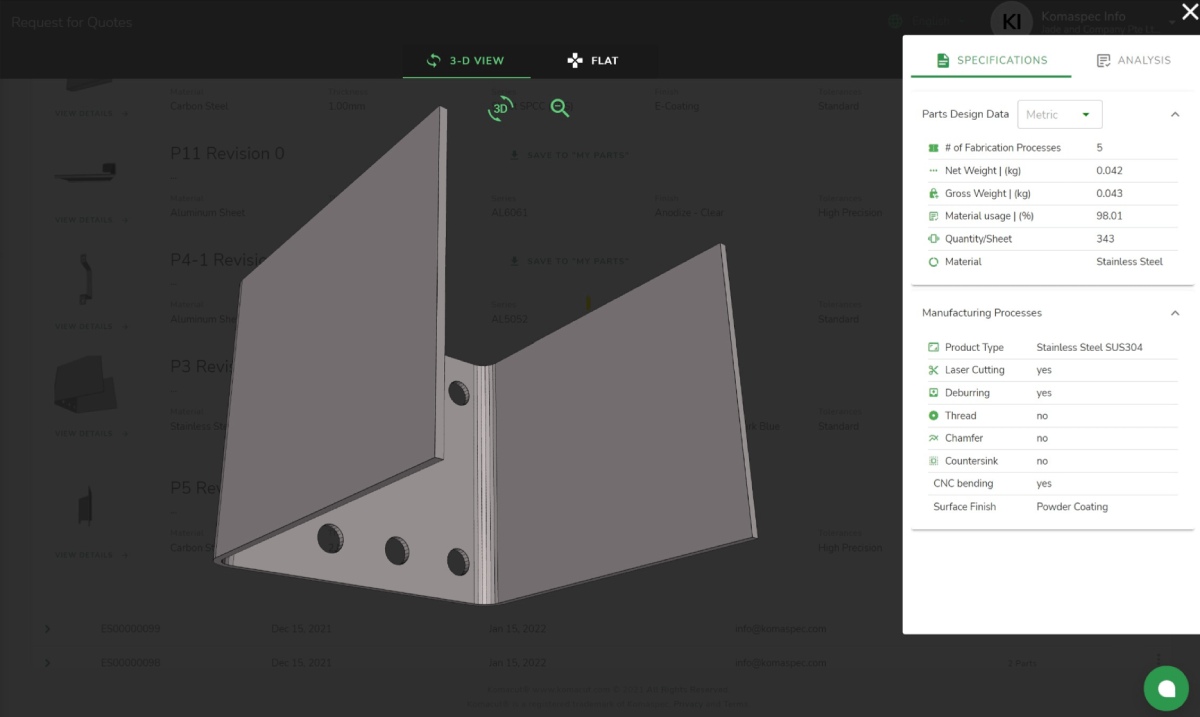
Fig. 2: Real-time DFM Analysis at Komacut
Drawing Formats
Generally speaking, if you have 3D drawings as well as 2D drawings, you should include both your 3D drawings and your 2D drawings.
- Ideally, each drawing file should be in triplicate:
- 3D Drawing Format – to allow for nesting, part simulation, etc.
- 2D Drawing Format – optional, but often helpful
- PDF drawing print – this will often contain important information such as material specifications, part finishing and tolerances
- Drawings will need to be converted to a flat pattern for fabrication, however, and 2D drawings are far more useable in sheet metal manufacturing.
- Where 3D drawings are used, they should be made with a sheet metal module, and good design practices should be followed so that the 3D dimensions match the 2D design. You can read more about CAD software and flat pattern designs in this Autodesk article.
- DXFs can be provided for laser parts, but you should be aware that they cannot fully define bending requirements. Read our article about DXF files and laser cut parts.
- Note that in case of discrepancies between the 2D and 3D designs, the 2D designs will prevail.
Komaspec
Our team of engineers and technicians here at Komaspec have more than 20 years’ experience in sheet metal fabrication in China. We’d be glad to review your product design together with you and provide detailed design feedback, including design for manufacturability feedback. Our analysis will help reduce manufacturing and tooling costs as well as improve functionality.
Frequently Asked Questions
What CAD software should I use to make sheet metal product drawings?
There are lots of different types of CAD software available for sheet metal product design. Free software is available for professional use, such as FreeCAD. There are also more expensive and advanced software packages available as well.
The features on offer vary between software brands, and it’s a good idea to shop around before you buy a CAD software package. The most advanced software is expensive and comes with high computational requirements. It’s normally best to find a balance between cost/computational requirements and your needs.
Read more about CAD software for sheet metal product design here.
What is design for manufacturability in sheet metal design?
Design for manufacturability is any design that takes best practices for manufacturing processes into account. Good design for manufacturability will result in a product design that allows a manufacturer to create a product as efficiently as possible, taking into account the equipment and resources they have and the procedures they follow, minimize processing and material waste, and with tolerances which are achievable.
CAD software can be a great help when it comes to achieving design for manufacturability. Some software packages come with very advanced features, making it easier to find the cheapest and easiest ways to manufacture a product.
What file format should I provide sheet metal product designs in?
Different manufacturers and different parties involved in sheet metal product design will use different file formats. Where file formats do not translate between different systems, important information can be lost. As such, it’s important to ensure that everyone involved works with compatible file formats.
- Common formats include PDF, DWG, DXF, STEP, IGES, Parasolid, STL, VRML, X3D and COLLADA.
- A good idea is to default to STP or STEP as these are the most “universal” formats for manufacturers to use
- STEP is a CAD file format standard used to share 3D models between different CAD systems. Here’s more information on STEP.
Best practice is to speak to your manufacturer and ascertain their file format requirements before sending designs.