Creating DXF Files for Laser Cut Parts
Laser Cutting Technology
When it comes to precision fabrication and manufacturing, laser cutting is the top choice. This burr-free cutting technology can produce accurate and precise cuts up to the order of just a few microns. Modern Fibre laser cutting technology is effective in many different materials such as ferrous and non-ferrous metals, plastic, wood, and paper with thicknesses that range from 0.5 mm up to 20+ mm.

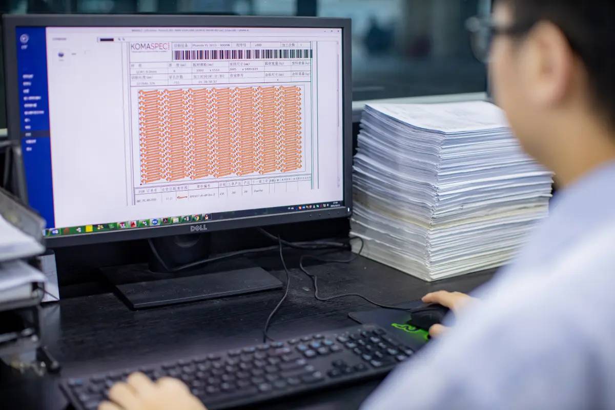
Fig. 1: Laser Cutting Sheet Metal at Komaspec
CNC stands for Computer Numerical Control. This is the principle on which laser cutters operate. A drawing file is created using one of many software packages available - discussed in the next section. This is then transformed into g-code, the language the CNC machine uses to interpret drawings.
This g-code file contains cut path information such as lead ins, part geometry, cutting speed and power settings. Specialized laser cutting software is used to produce g-code files based on the material and parts to be cut, to ensure optimum part accuracy, sheet utilization and speed.
In this guide, we’ll walk you through the steps to creating a usable laser cut part design file, and the top tips and best practices to avoid common errors.
Laser Part Drawing Formats & Software
When incorporating laser cutting and fabrication, there are multiple software tools that can be of assistance. Some of the most common solutions include:
- SolidWorks:One of the most extensively used design and assembly software packages. It has a complete set of modeling tools and can easily convert 3D models into 2D. In addition to this it includes a comprehensive sheet-metal environment, allowing the easy calculation of bend lengths, radii etc. (“3D CAD Design Software”).
- AutoCAD:AutoCAD is one of the earliest CAD software. It is easy to use for both 2D and 3D modeling. one benefit of AutoCAD is that it offers a simple way to edit and check 2D DXF files once exported from 3D software (“AutoCAD Software | Autodesk”).
- Fusion360: Like SolidWorks, Fusion360 is intended to produce designs and models of 3D parts. It has the same modeling capabilities but is not as assembly-driven as the former. It is a solution often favored by hobbyists and start-up companies due to its competitive pricing (“Software for 3D CAD, Modeling, Manufacturing, Industrial Design, Electronics and Mechanical Engineering.”).
- SketchUp:SketchUp is much simpler than the previous ones. It is not a true design software but is enough to create 3D and 2D shapes. often used by architects and creative industries for renders of environments (“3D Design Software | 3D Modeling on the Web”).
All of these applications allow engineers and draftsmen to easily create detailed and complex patterns which would otherwise have been incredibly time-consuming in traditional formats.
Order and track sheet metal components online through Komaspec's on-demand sheet metal fabrication platform.
File Types
Different CAD packages use different native file types, these are often unique to the particular program or program company. Helpfully when creating Laser cutting designs, they can often be interchanged by use of conversion tools. Examples of proprietary file types include .SLDPRT, .SLDASM and .SLDDRW, which are part, assembly and drawing files respectively, unique to Solidworks Software.
2D CAD software produces various different file formats, collectively known as vector files. A vector file is a computerized image mathematically defined by calculated positions of points and lines on a coordinate system. The most distinct feature of a vector file is that it has an infinite resolution. This allows the image to be scaled up or down to any size without losing quality.
The opposite of a vector file is the raster or bitmap. These are images made from a collection of pixels. Since the pixels used in creating the image have an associated number and arrangement, the resolution of a raster file is limited.

Fig. 2: Vector vs Raster
A good suggestion is to consider using DXF, or Drawing Exchange Format, it is a type of vector file format developed by Autodesk. It is intended for data collaboration between AutoCAD and other drawing software. Almost all CAD software can import and export DXF files using CAM or DXF plugin. This makes the DXF file a universal format for manufacturers all around the world.
Initial Artwork
The first step in laser cutting is obtaining and creating the pattern or artwork. Artwork can be produced from many different sources such as a text-based document, an image, or a CAD model. Those produced from software capable of exporting vector files are easily interpreted by laser cutters.
Converting Raster Files
Artworks in raster file formats such as BMP, JPEG, and PNG require an additional process of converting the images into vector files. This is typically done using the trace command of drawing software such as Adobe Illustrator and Inkscape. There are other tools available that will scan your image and convert it automatically, these programs work best with clear, simple raster drawings.
If your image is blurry, multicolored, or very complex, it might be easier to trace the drawing in AutoCAD. It is a crude but effective way to replicate a drawing, but it is time consuming. The process is as simple as inserting your image into the drawing space, and using the relevant line tools; Line, Spline, Arc, etc, to trace the edge of the object.
Bear in mind, your cut lines need to be one continuous with no overlaps, to be processed effectively in the Laser programming software. A handy way to check this, is to use the Hatch Tool to attempt to color your shape, if the tool fails, there is a gap somewhere between points. New Autocad packages will highlight this for you.
Guidelines for Creating DXF Laser Cut Patterns
Now that an initial artwork is acquired, it must then be finalized using a set of best practices for producing a proper vector pattern. In creating the pattern, it is important to note several limitations and restrictions to the cutting process. It helps to visualize how the laser cutter will perform the cutting on the blank workpiece. Here are some guidelines for creating the pattern.
1. Properly scale the drawing
In any project involving fabrication software, it is important to check if the pattern is at the correct scale. The usual artwork scale is 1:1. Using the right scale is critical especially if the finished part is designed to mate with other objects in an assembly. The pattern may appear correct on the drawing board but come out wrong after cutting.
For this reason, it is often advisable to include a rough description of the part dimensions in the file name, to allow the CNC programmer a way of checking your part is to the correct scale.
2. Use the right units
Using the correct units is as important as properly scaling the pattern. If the desired laser-cut part is in inches, the drawing must be in inches. Do not confuse imperial and metric.
3. Choose between negative or positive image
A negative image is a design style in which the patterns are removed from the workpiece. The material left becomes the final product. In a positive image, the material removed from the workpiece becomes the product.

Fig. 3: Negative and Positive Designs
Both of these styles have their pros and cons. A negative image is much easier to fabricate but consumes more material. This style is mostly used in signages, stencil templates, and nameplates. Positive images, on the other hand, are harder to work with, especially when used the same way as negative images. They are mainly used in producing parts of an assembly.
4. Convert annotations into shapes
As much as possible, reduce the design into simple lines. If the design contains annotation objects such as texts and symbols, these items must be converted accordingly. Active textboxes cannot be interpreted properly by the laser cutting machine. Usually, the machine excludes unconverted annotations from the cutting pattern.
5. Stencil the design
It is imperative to know that any closed region will be cut off from the final part. To include the “islands” or sections inside the cut-outs of the pattern, it must be connected to the other parts using narrow sections. These narrow sections, called “bridges”, are not cut out from the design.
One tip is to load and use a font designed for stencils in a program such as Desk Engrave. This creates a DXF file you can cut, copy, and paste into your design, with letters already containing the required bridges.
Stenciling is not required for laser etches. In laser etching, only a partial cut is made, and material is still present underneath to hold the islands in place.


Fig. 4: Stencil the Design
6. Cut-outs must be bounded by a continuous line
All shapes to be removed from the final piece must have a continuous outline. Gaps can create open contours which will prevent the laser cutter from completing the cut-out. The cutter will execute the cut, but the result will be different from what was intended. Some laser cutting software and systems can prompt the user if an open contour is detected. A file can be checked for line completion using the Hatch tool as mentioned earlier.
7. Avoid intersecting and overlapping lines
This issue is quite common in designs dealing with complex and composite shapes. Intersecting and overlapping lines produce undesired cut-outs and unclean cuts. Like how an open contour is formed, separate line segments are sometimes hard to merge flawlessly. This is a problem especially when the drawing software is not equipped with proper CAD tools.
8. Take note of the laser cutting kerf
When the laser cuts the workpiece, some of the material is removed from the material. The amount of material removed is called the kerf. It has a width that can affect the tolerances of the design. This becomes an issue, especially in small patterns. The dimensions of the pattern must be adjusted to compensate for the kerf.
9. Don’t create multiple shapes
There is no need to create multiple copies of the finished product within the file. The proper layout usually depends on the type and thickness of the material and capabilities and settings of the laser cutting machine. This job is best turned over to the fabricator.
Additional DFM (Design for Manufacturability) Checks
A designer sometimes must accept that not all aspects of the design make it to the final product. If the objective of the project is mass production, its fabrication method must be optimized to avoid any unnecessary operating costs.
Since the fabrication method is already decided, the other considerations left are:
- Complexity of the design: The design must be as simple as possible. Avoid any non-standard features such as custom joints, edges, and fittings.
- Type of material: The material must be selected not only for its properties but also for its cost and availability. Some materials are also difficult to cut making the production process much more expensive. Our Materials Guide can be found
- Product assembly: It is sometimes best to establish tolerance limits between mating parts. This is to avoid any clashing or loose components in an assembly.
- Maximum Size: refer to the Komacut table
- Minimum Hole Size: The limit on hole size for laser cutting is typically 1:1, that is that the hole diameter should be equal to or greater than the material thickness. Holes smaller than the thickness diameter may result in poor dimensional accuracy. In some cases, holes can be produced at 0.5x material thickness. Refer to our laser cutting guide for more information. Small holes may need secondary processing such as drilling.
- Ensure the correct orientation: when Laser cutting Aluminum or Stainless Steel, it is important to note if any particular finish is required, and what way up the parts are to be cut. These materials can be supplied pre-polished, on one or both sides.
For additional DFM tips and processing guidelines, check out this guide on DFM for Laser Cutting.
We are glad to review your product design together and help you select the fabrication process that best suits your product’s needs.
Works Cited
- SOLIDWORKS, solidworks.com. Accessed 7 Apr. 2022.
- “AutoCAD Software | Get Prices and Buy Official AutoCAD 2023 | Autodesk.” Autodesk, 31 Mar. 2022, autodesk.com.hk/products/autocad/overview/.
- “Software for 3D CAD, Modeling, Manufacturing, Industrial Design, Electronics and Mechanical Engineering.” Fusion 360, autodesk.com/products/fusion-360/overview. Accessed 7 Apr. 2022.
- “3D Design Software | 3D Modeling on the Web.” SketchUp, www.sketchup.com. Accessed 7 Apr. 2022.
- “Vector vs Raster Files.” Graphic Design Services, http://www.seekacreative.co.nz/resources/vector-vs-raster-files. Accessed 26 Apr. 2022
- “Beginner’s Guide for Laser Cutting Stencils.” Jackforge.Com, 7 Sept. 2020, www.jackforge.com/laser-cutting-stencils.
- “5 Key Design Tips for Laser Cutting DFM.” Komaspec, komaspec.com/about-us/blog/5-key-design-tips-for-laser-cutting-dfm/. Accessed 7 Apr. 2022