How to Choose the Right Sheet Metal Fabrication Process
- Overview
- Sheet Metal Cutting and Forming Processes
- CO2 and Fiber Laser Cutting
- Plasma Cutting
- Water Jet Cutting
- Mechanical Cutting
- CNC Sheet Bending
- Shearing
- Roll Forming
- Precision Manual Stamping
- Precision Progressive Stamping
- CNC Punching
- How to Select Sheet Metal Cutting and Forming Processes
- Process Cost
- Precision Requirements (Tolerance)
- Tooling Requirements
- Thickness Requirements
- Minimum Order Quantity
- Is Design Iteration Required?
- Necessary Lead Time
- Sheet Metal Joining and Assembly Processes
- Welding
- Riveting
- Fasteners
- How to Select a Sheet Metal Joining and Assembly Process
- Design Requirements
- Strength Requirements
- Lead Time and Production Speed
- Production Volume
- Further Finishing Processes
- Komaspec’s Sheet Metal DFM & Fabrication Services
Table of Contents
- Overview
- Sheet Metal Cutting and Forming Processes
- CO2 and Fiber Laser Cutting
- Plasma Cutting
- Water Jet Cutting
- Mechanical Cutting
- CNC Sheet Bending
- Shearing
- Roll Forming
- Precision Manual Stamping
- Precision Progressive Stamping
- CNC Punching
- How to Select Sheet Metal Cutting and Forming Processes
- Process Cost
- Precision Requirements (Tolerance)
- Tooling Requirements
- Thickness Requirements
- Minimum Order Quantity
- Is Design Iteration Required?
- Necessary Lead Time
- Sheet Metal Joining and Assembly Processes
- How to Select a Sheet Metal Joining and Assembly Process
- Further Finishing Processes
- Komaspec’s Sheet Metal DFM & Fabrication Services
Overview
There are many different choices to make when using sheet metal to fabricate a product. Decisions have to be made at the design stage, choices such as material selection, material thickness or what kind of finish is required. As part of the design process, it’s important to consider which production technologies might be used when manufacturing the part, and considering the impacts of that process on the part design. The choice of production processes will impact part price, tolerances, part geometry, lead time, tooling requirements, even part finish and strength. Often, the initial part design will need to be revisited after thinking through the implications.
Sheet metal fabrication processes can be classed as two main groups:
- Cutting and forming processes
- Joining and assembly processes
Not all processes will suit all sheet metal parts and assemblies. For most parts and assemblies, however, there will be a number of potential choices. Different fabrication processes will produce slightly varying results in terms of the finished design approach. As well as this, different processes will also come with different costs, production times and other production limitations or opportunities that need to be considered.
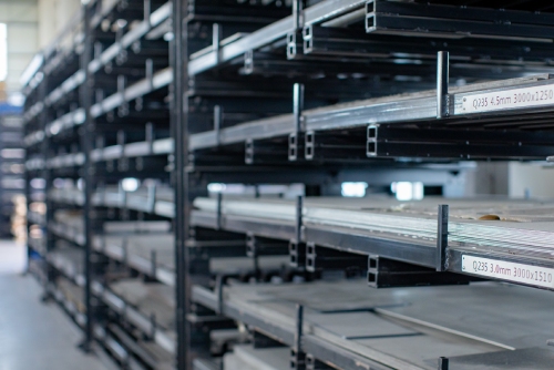
Sheet Metal Cutting and Forming Processes
The first group of sheet metal fabrication processes we’ll look at is cutting and forming processes.
In cutting and forming processes, sections of sheet metal are cut, bent, molded or otherwise manipulated to meet design specifications. The simplest example of a cut or formed piece of sheet metal is an angle iron. To create an angle iron, a long, straight piece of sheet metal is bent (formed) in one direction.
Cutting and forming processes are often the first stage of processing that sheet metal products undergo, coming before joining and assembly processes.

Most cut or formed sheet metal parts are more complicated than angle irons, meaning several different cutting or forming processes are applied to a single piece of sheet metal over several stages. A single cutting or forming process may be repeated in multiple stages, or more than one cutting or forming process may be used. A sheet metal piece may have several laser cuts performed on it, and then it may be bent at more than one point, for example.
Even parts as simple as an angle iron may be produced by combining two to three different processes. Angle irons can be produced through laser cutting and CNC bending, stamping, shearing and forming, etc.
In this section, we’ll look at the following cutting and forming processes:
Cutting
- Laser Cutting (CO2 and Fiber Lasers)
- Mechanical Cutting
- Water Jet Cutting
- Plasma Cutting
- Shearing
Forming
- CNC Sheet Bending
- Roll Forming
- Precision Manual Stamping
- Precision Progressive Stamping
- CNC Punching
CO2 and Fiber Laser Cutting

Laser cutting uses a high-powered, industrial laser to cut sheet metal into the required shape and dimensions.
There are two broad categories of laser cutting: fusion cutting and ablative laser cutting. In fusion cutting, the laser melts the material, and high-pressure gas is used to sheer the melted material away. In ablative laser cutting, a pulsive laser is used to remove material layer by layer.
Modern laser cutters are either CO2 lasers or fiber lasers. CO2 lasers use infrared light to cut materials. They are less powerful and slower than fiber lasers, but they leave a smoother surface finish when cutting thicker materials. Fiber lasers are faster, generally more powerful, and can cut thicker overall material.
Advantages:
- Faster and more efficient than mechanical cutting methods.
- Smoother surface finish than mechanical and most other computer-controlled methods.
- Highly accurate, precise results that accommodate tight tolerances.
- No custom die required, and diverse shapes can be obtained.
- Works on a wide variety of metals as well as other materials.
- Accommodates a wide range of material thicknesses.
- Well suited for metal annealing, etching as well as engraving for serial numbers, barcodes, part marking, etc.
- With modern CNC controls, complicated individual cuts are possible as well as complicated production runs.
Disadvantages:
- Potential for heat induced structural changes to occur to the material, impacting the final product.
- Reflective materials can be difficult to cut
- Laser cutting is not suitable for most plastics or woods
- Requires in-process adjustment when cutting sheet metal with varying thicknesses.
- Work hardening of the edges may require additional processing before treatments like powder coating or painting can be applied.
- Other cutting methods may be better for high-volume production.
Plasma Cutting

Plasma cutting uses an accelerated jet of hot plasma to cut through electrically conductive material, such as metal.
During plasma cutting, compressed gas is forced at high speed, in a jet, towards the material being cut. An electric arc is created in the gas between an electrode in the cutter and the electrically conductive material being cut. The electricity ionizes the gas and as electricity passes through it, creating a jet of plasma that becomes heated enough to melt the material being cut. Temperatures in the stream of plasma can reach over 20,000 °C.
Because the material being cut needs to be electrically conductive, not all materials can be cut with a plasma cutter. Common materials cut with plasma cutters are steel, aluminum, brass, copper, nickel and titanium.
Advantages:
- Very neat cut edges are possible.
- Fast cutting speeds are possible compared to many alternative cutting methods.
- Narrow kerf widths.
- Good levels of precision.
- Cheaper than laser cutting and water jet cutting.
Disadvantages:
- Not suitable for non-electrically conductive materials.
- The high temperatures can cause problems in the material being cut – less suitable for thin and medium-thin sheet metal parts.
- Plasma cutters produce radiation, meaning that workers have to wear protective equipment.
- Less precision and slower cutting speeds than laser cutting.
- Post-processing may be required at cut edges.
Water Jet Cutting

Water jet sheet metal cutting uses a highly pressurized mixture of water and abrasive material to cut metal. The mixture is forced, by a hydraulic pump, through a system of pipes that pressurizes the water up to as much as 60,000 psi. The water is released as a thin jet, that is similar in essence to a laser, and this jet cuts the surface it lands on through abrasive action.
Water jet cutting is highly accurate and versatile, and modern machines can be programmed to produce repeated, identical cuts across an entire production run.
The big advantage water jet cutting has over other comparable cutting methods (laser and plasma cutting) is that the process does not produce as much heat. Where laser cutting or other heat producing methods will cause a problem for a sheet metal part, water jet cutting provides an alternative.
Water jet cutting can be done on materials other than metal and is often used on stone, glass, plastics, wood or rubber. For softer materials, pure water can be used as a cutting medium, without the addition of abrasive material.
Advantages:
- Highly accurate, precise and intricate cuts are possible.
- Heat-induced structural effects on sheet metal are avoided.
- Small kerf widths are possible.
- Suitable for a range of metal types as well as other materials.
- Produces smooth cut edges, reducing the need for post-processing.
- On large production runs, water jet cutting can be cost effective.
- Thick pieces of metal can be cut – it’s possible to cut up to 300mm with water jet cutting, which is more than laser cutting.
- Water jet cutters can be combined with software to automatically manage complicated production runs.
Disadvantages:
- Cutting times are slower than with other methods.
- Thick cuts are not as clean as other cutting methods – tapering often occurs down the cut edge.
- For the best finish results, post-processing will be required.
- Can be more expensive than other cutting methods.
- Less suitable for small-scale production runs due to cost and set up times.
- Manufacturers with water jet cutting equipment may be harder to find.
- Less suitable to engraving and annealing.
Mechanical Cutting

In mechanical cutting, machines with parts that have power-driven, moving cutting edges are used to shape metal to match design specifications. The cutting edge of the machine simply removes material from a piece of sheet metal through mechanical action. The methods employed are less sophisticated than up to date methods but can be useful in some manufacturing scenarios.
Some examples of mechanical cutting machines are lathes, milling machines and drill presses.
In a lathe, a piece of metal being cut is spun and moved against a stationary blade that performs a cut. Milling machines work in the opposite way to lathes. A cutting blade is spun and moved against a piece of sheet metal, and it performs a cut as it comes into contact with it. With a drill press, a drill piece is used as a cutting edge and is pressed into a piece of sheet metal to perform a cut.
Mechanical cutting methods all vary according to how the piece of equipment being used performs a cut and work in a relatively straightforward way. Some other examples of mechanical cutting machines are grinders, saws and planers.
Advantages:
- Mechanical cutting methods can be fast to set up, making them useful for small-scale production runs.
- A high level of accuracy is possible with modern cutting machines, and they can be useful where a high level of precision is required.
- Can be used on a wide variety of metal types as well as other materials.
- Many factories will have these machines available for use.
- Custom tooling usually isn’t required.
- It is easy to produce prototypes with mechanical cutting methods.
- Some mechanical cutting methods may have reduced heat induced structural effects on sheet metal parts.
Disadvantages:
- It may not be possible to perform certain cuts with mechanical cutting machines – lathes cannot cut in the center of a workpiece, for example.
- Several different mechanical cutting processes may need to be combined to complete the production of a part.
- Post cutting processing is often required with mechanical cutting.
- Specialist labor may be required.
- Slower processing times may be unsuitable for large-scale production runs.
- There may be variation between parts, depending on the exact production methods used.
CNC Sheet Bending

CNC sheet bending uses a CNC press break or a CNC folding machine to bend metal into two or three-dimensional shapes.
This sheet metal fabrication process can be used to bend large or small sheets of metal, and high-quality pieces can be fabricated quickly. CNC sheet bending can be used in the early stages of fabrication, or it can be used to adjust a finished or near-finished product. Dies are available for standard angles and operations, meaning custom tooling may not be required.
Advantages:
- Highly accurate process, ideal for parts requiring high precision.
- Can produce large volumes in a short time.
- Low-cost basic process with minimal tooling costs.
- Suitable for high or low volume production.
- Can create multiple, custom shapes through a series of bending processes.
- Standard punches and dies are available, including in V and U shapes.
Disadvantages:
- The process can cause indentations or marks on the product linked to the point at which the bend is made.
- While bending can be roboticized, it can be labor-intensive, which makes is less suited for high volume production.
- Custom tooling is required for specialized bending projects.
- Bends need to be positioned on the sheet metal part to allow it to fit into the equipment without slipping.
- Fractures can occur when hard metals are bent parallel to the rolling direction of the sheet metal.
- Holes, slots or other features close to the bend can become distorted.
Shearing

With shearing, force is applied with either a die, punch or blade to sheet metal, and this causes it to fail and separate in the location of the desired cut. Shearing is typically used for straight line cuts but can also produce angled cuts.
Advantages:
- Can produce very long, straight lines.
- Works well with soft metals.
- Cost effective for high output projects.
- Good choice for cutting small lengths or different shaped material.
Disadvantages:
- Limitations in the type and intricacy of cuts (used mostly for straight cuts).
- The process can create burrs or other imperfections at cut ends.
- Not suitable for all materials, including hard metals and parts with very large diameters.
- Slower and less precise than other cutting methods.
Roll Forming

Bending Rollers (Barnshaws)
In roll forming a long strip of sheet metal is passed through a series of paired rollers. Each pair of rollers performs a partial bend on the strip of sheet metal. As it passes through the rest of the rollers, it is continuously bent until it meets the final, specified shape. The strip of sheet metal can then be cut into the required lengths to provide a finished part.
To create a unique shape through roll forming, it’s necessary to create a unique set of rollers. Custom roll sets are often needed, which can be costly and complicated to produce. This form of production is, however, useful for large-scale production runs because of the fast production speeds and low ongoing production costs.
Better results can also be obtained than they can through extrusion, which is a rival process. Thinner and stronger profiles are possible, for example. Often, no post-processing is required with roll forming as well, and the sheet metal part is ready to as soon as it’s cut to size. By performing bending at multiple stages (at each roller), it’s also possible to produce highly complex shapes through roll forming. Roll forming may, in fact, be able to produce shapes that aren’t possible through other production methods.
Advantages:
- Fast production speeds.
- Low cost over large production runs.
- Minimal post-processing required.
- Secondary processes, such as punching or cutting, can be incorporated into the rolling process.
- Improved results compared to extrusion for certain sheet metal parts.
- Highly complicated shapes may be possible through a relatively simple production process.
- Can provide an alternative where stamping is not possible due to engineering constraints.
Disadvantages:
- Complicated and sometimes expensive production set up process.
- Metal springback may create difficulties during production.
- Certain shapes cannot be formed through rolling.
- The end pieces in a strip of sheet metal can flare out and be unusable or poor quality.
- A large amount of floor space is required at the production facility.
- Can be inappropriate for narrow or short parts.
Precision Manual Stamping

Stamping is the process of using a mechanical or hydraulic stamping press to form metal. When metal is formed in stamping press, a die is used to bend, punch, blank, coin, emboss, stretch, curl or otherwise process the piece of metal. Customized dies are created for individual production runs. Dies are highly specialized and need to be manufactured very precisely before being used in production.
Simple examples of the use of stamping are for forming shapes, letters or images in sheet metal through bending. For these productions, more simple dies can usually be used. In more complex projects, where processes like stretching, hemming, flanging or curling occur, dies are more complicated. Stamping presses can even mold metal into highly complex forms, such as when four-slide stamping is used to create a four-sided shape.
While creating dies can be time consuming and expensive, stamping machines work very quickly and very accurately. Stamping can be a highly cost effective and fast production method for large scale production runs.
Advantages:
- Fast and cost-effective for medium to high volume production.
- Accurate and precise for complex shapes, producing identical pieces.
- Once the die is created, thousands or tens of thousands of identical parts can be produced very quickly.
- Well suited to small parts requiring micro-precision (±05mm linear tolerances or better).
- Versatile process that can include punching, blanking, embossing, flanging, bending or coining.
- Leftover material can be recycled.
Disadvantages:
- A long pre-production time is needed to make the custom die – production of dies can take upwards of 45 days.
- Changes needed once the die is created are costly and impact the production schedule.
- Stamping tooling is relatively fragile – repeated changes can result in shortened tool lifespan.
- Errors in the die will result in errors with an entire production.
- Pieces may require additional sheet metal fabrication processes, including deburring, tapping, reaming or counterboring.
- Less cost effective for smaller order production (generally thousands to tens of thousands of pieces minimum).
- Stamping tooling undergoes tremendous forces – it must be regularly maintained and monitored.
- Must use materials that are malleable enough to form without breaking.
Precision Progressive Stamping

With precision progressive stamping, a coiled strip of metal is passed through a stamping machine that contains a series of dies arranged in a sequence. Rather than having a single die processing the metal in one stage, as in manual stamping, processing occurs over several stages through the sequence of dies. As the strip of metal passes through the machine, bending, punching, blanking, coining, embossing, stretching, curling or another form of processing happens as the strip of metal passes each die. At the final stage, the strip of metal is cut to provide a finished part.
Progressive stamping is used where it isn’t possible to process metal with one die or where other production methods aren’t suitable. The big benefit with progressive stamping is that it can be used to create highly complex parts at fast speed. Dies can be created to produce a huge variety of forms with a high degree of accuracy, and stamping machines operate extremely quickly.
As with manual stamping, a great deal of care is needed in the creation of the dies, and they can also be costly to produce. Where complicated parts need to be created in large volume, however, progressive stamping can be very useful.
Advantages:
- Can be used to create more complex shapes than manual stamping or other production methods.
- Cost-effective for high volume production (tens to hundreds of thousands of parts) - due to very low levels of labor involved, the per piece cost for high volumes is very low.
- Accurate production of complex shapes.
- Fast production speeds.
- Well suited to small parts requiring micro-precision.
- Versatile process that can include punching, blanking, embossing, flanging, bending, coining or other processes.
- It is possible to reduce scrap production through careful design of parts and dies.
Disadvantages:
- Custom dies can be time consuming to produce – in many cases, more than 50 days lead time is needed before production can start.
- Dies and other tooling is also costly to produce, requiring a high upfront investment.
- If changes are needed after the die is created, this will be costly and disruptive.
- Stamping tooling is relatively fragile – repeated changes can result in shortened tool lifespan.
- Any errors in the die will result in errors with an entire production.
- Pieces may require additional sheet metal fabrication processes, including deburring, tapping, reaming or counterboring.
- Stamping tooling undergoes tremendous forces – it must be regularly maintained and monitored.
- Must use materials that are malleable enough to form without breaking.
CNC Punching

With CNC punching, a punch press is used to push sheet metal into a die to create holes or cut-outs. CNC punch machines can also be used for secondary processes like tapping, blanking, forming, extruding or deburring.
Advantages:
- Stronger cutting power than some other methods, making it suitable for a wide variety of metals.
- Fast and cost-effective way of punching holes, squares, slots, notching or other shapes into flat metal.
- Well suited to medium to large quantities.
- Good levels of precision and uniform cuts.
- Standard punches are available for use.
- Can produce intricate designs, using overlapping cuts, or 3D forms such as dimples or countersinks.
Disadvantages:
- Not well suited to complex shapes.
- Edges will have burs and may require secondary finishing.
- The diameter of the holes generally shouldn’t be smaller than the sheet metal gauge.
How to Select Sheet Metal Cutting and Forming Processes
The selection of cutting and forming processes for sheet metal parts depends on both design requirements and production limitations.
Different cutting and forming processes produce sheet metal parts with slightly varying physical characteristics. First of all, it’s important to choose a process that will produce a sheet metal part that meets physical design requirements. Different processes also come with different production costs, production times and levels of difficulty in manufacture.
Usually, the best thing is to pick the processes that deliver what’s needed in terms of the design requirements at the minimum cost, on time and with as little hassle as possible.
The most important things to consider are:
- Process Cost
- Precision requirements (tolerance)
- Custom tooling requirements
- Bend thickness requirements
- Minimum order quantity
- Necessary lead time
| Process | Best Used For | Precision/Tolerance Level | Custom Tooling Required? | Thickness | Minimum Order Quantity | Typical Lead Time |
|---|---|---|---|---|---|---|
| Laser Cutting | Small to large parts with every geometry possible | Linear ±0.10mm Angular - |
No | 0.5mm to 20.0mm | 1 Unit – prototype 100s to 1ks - MP |
≤5 days for sampling, 10 days for MP |
| CNC Sheet Bending | Small to large parts with straight angle geometry, multiple bend possible | ±0.18mm | No, unless special form required | 0.5mm to 20.0mm | 1 Unit – prototype 100s to 1ks - MP |
≤5 days for sampling, 10 days for MP |
| CNC Punching | Small to large parts with most geometry available, good for parts with multiple holes and embossed | ±0.10mm | No, unless special form required | 0.5mm to 4.0mm* | 1 Unit – prototype 100s to 1ks - MP |
5 days for sampling, 10 days for MP |
| Manual Stamping | Medium volume production with tight tolerances, restricted geometry | ±0.05mm to 0.10mm | Yes; from 250 USD to 50k USD+ | 0.5mm to 4.0mm* | 3 to 5k units and above | 30 to 40 days for tooling; 15 days for production |
| Progressive Stamping | Medium volume production with tight tolerances, restricted geometry | ±0.05mm to 0.10mm | Yes; from 10k USD to 100k USD+ | 0.5mm to 4.0mm* | 10k units and above | 45 to 55 days for tooling; 15 days for production |
| Shearing | Thin material with simple geometry (straight lines) and low tolerances requirements | ±0.50mm | No | 0.5mm to 4.0mm* | 1 Unit – prototype 100s to 1ks - MP |
≤5 days |
Table 1: Manufacturing Processes Overview
* Higher gauge may result in deformation or reduced precision
Process Cost
Process cost is often the most important factor to consider when selecting the right sheet metal fabrication process.
As a basic approach, the best thing is to choose the cheapest production method that will produce parts to at least the minimum quality standards. There is no reason to over-manufacture parts at additional cost. The chosen production method needs to be able to manufacture parts to design specifications (dimensions, material use, material thickness, correct finish, etc.) and within tolerance ranges at the best price possible.
Making the right choice cost-wise can, however, become more complicated because different production methods will vary in cost according to various factors related to the manufacturing process. The main factors to consider are the volume of production and the capabilities of your manufacturer.
- Production volume – production volume is a critical factor because some methods of production are cheap over high volumes but expensive over small volumes. Stamping and progressive stamping, for example, require a high initial investment for tooling. This makes them unsuitable for small-scale production runs. Over high volumes of production, however, these production methods are far faster and more cost effective than others.
- Manufacturer capabilities – Manufacturers that specialize in certain production methods may be able to reduce costs for using them. This can be useful where using a particular production method will have benefits in terms of output quality or speed of production.
The table below presents a basic guide to manufacturing cost for different production methods:
| Process | Tooling Cost | Part Cost |
|---|---|---|
| Laser Cutting | None | Medium |
| CNC Sheet Bending | None to Low | Medium |
| CNC Punching | Low | Low to Medium |
| Manual Stamping | Medium | Low |
| Progressive Stamping | High | Very Low |
| Shearing | None | Medium |
Table 2: Manufacturing Processes Cost Overview
Precision Requirements (Tolerance)
One of the most important things to consider when choosing a cutting or forming process is the level of precision that is required of the finished sheet metal part. The levels of precision that are achieved during production are important when it comes to the performance of the finished part as well as further assembly and alignment.
Tolerance is a measurement of the acceptable variation between an initial part design and an actual finished part. This measurement is used to determine precision requirements.
Most importantly:
- It’s essential to choose a cutting or forming process that will produce a part within the minimum tolerance levels.
- It may be beneficial to choose a process that is less precise but still within tolerance levels.
Achieving higher levels of precision is usually more expensive, and it can mean using more complicated and time-consuming production methods. As a result, the best approach is usually to choose processes with lower levels of precision wherever possible. Unnecessary precision may add no benefit at extra cost, time and effort.
Where high levels of precision are required, with certain processes, it’s possible nowadays to achieve precision levels of ±0.05 mm.
As well as the choice of cutting or forming process, there are other things that also influence precision levels:
- Material selection –thickness and shape accuracy
- Metals are supplied to manufacturers within thickness tolerance ranges because precision varies in the initial production of sheet metal. This is even the case with high precision methods of production.
- Some materials will have greater variability in flatness or material consistency – this can impact angular tolerances and springback.
- Equipment precision
- Fabrication company capabilities
Tooling Requirements
With some sheet metal cutting and forming processes, custom tooling is required before manufacturing gets underway. It may also be necessary to buy additional equipment for certain production runs.
Examples of customized tools are dies, punches or molds of specific sizes and dimensions. These are made to match the specific requirements of a part being created in a production run.
Stamping is one process where custom tools are almost always required. They are used in other processes, however, with punching and bending being other examples of where they may be used.
Custom tools can be expensive to make in some cases, and a great deal of care is needed to ensure they are accurate. For this reason, there are often lengthy qualification processes, CMM measurement of tooling, 3D and 2D scanning of parts, and part measurement before tools are certified for use in production.
In some production processes, such as shearing, tools are rarely used, and in other processes standardized tools are often available. Where standardized tools are available, this negates the need to create custom tools. Custom tools do allow for highly individualized modes of production, but they take time to create and can add cost to the production process.
Roll forming is another example of a sheet metal forming process that may require custom tooling and equipment.
Thickness Requirements
The thickness of the sheet metal being processed in the production of a part is something that needs consideration. The main consideration is whether or not you will need to process thick pieces of sheet metal during production.
Thick sections of sheet metal can only be processed using certain methods. Of the methods we’ve discussed above, the only two processes that are capable of being used with sections of sheet metal over 4 mm are laser cutting and CNC bending.
Minimum Order Quantity
You may need to discuss minimum order quantities with your manufacturer before deciding on a cutting or forming process. It may be that your manufacturer is only able to use certain processes on large volume production runs.
Some processing methods are unsuitable for smaller production runs. Typically, this is where there are large costs or time requirements at the set-up stage of production. Stamping is one process that generally isn’t well suited to smaller production runs. This is because the time and expense that is needed in creating custom tooling and planning production procedures is often extensive. Other methods of processing may require expert labor or specialist equipment that can only be justified for a large order. This is why progressive stamping is the process of choice for high-volume sheet metal applications like automotive or consumer electronics.
On the other hand, if you have a relatively small production volume, semi-automated processes like laser cutting, or even manual processes like mechanical cutting may be better suited and faster.
Note that the exact minimum order quantities will vary between suppliers.
Is Design Iteration Required?
For designs which have not been fully prototyped or tested, it is not recommended to proceed with tooling or a long lead time process. It’s better to take the fastest possible approach to create physical samples and to be able to conduct field testing and certification. This is why initial samples and pilots are often done using laser cutting or similar processes - in case there are issues with the design, iteration is as simple as updating the drawing and recutting new pieces.
Once the design is proven and the product design and performance are stable, tooling can be cut for larger volume orders to reduce the product cost.
Necessary Lead Time
Another thing to consider, relevant to production requirements, is the lead time your manufacturer will need. This is the time it takes between a manufacturer receiving design requirements and them being able to begin production.
Where customized tools aren’t required and set up procedures aren’t complicated, lead times are reduced. With processes where designs can be fed straight into a production machine, such as laser cutting, lead times can be very short.
Other processes take much longer to set up. Where planning is needed, where custom tools are needed, where specialist equipment needs to be found or where staff need to be trained, for example, lead times will be longer. Large orders may also need a longer lead time because the manufacturer will need to plan to be able to free up resources.
Stamping is an example of a process that usually has long lead times. It typically takes 25 days to set up a stamping production run because of the need for custom tooling and careful production planning.
When it comes to prototype creation, it’s often possible to produce sheet metal part prototypes very quickly with the majority of cutting and forming processes. With laser cutting, bending, stamping and shearing, prototypes can often be produced in as little as an hour.
Sheet Metal Joining and Assembly Processes
Sheet metal joining and assembly processes are processes in which separate sheet metal parts are put together to form a final assembly. The parts that are put together have usually already been subject to other forms of processing, such as cutting or forming.
Finishing processes can be applied to parts before they are assembled, or they can be applied to complete assemblies.
In this section, we’ll look at the following joining and assembly processes:
- Welding
- Riveting
- Fasteners
Welding

Welding is a process whereby two or more parts are joined together through heating, pressure or both. As the parts cool, following the application of heat and/or pressure, a permanent bond is formed. Most people are familiar with the use of welding with metal, but it can also be used with thermoplastics and wood.
MIG welding and TIG welding are usually the best for sheet metal parts. This is because they occur at reduced temperatures, and this limits the effect high heat levels have on the metal. Where welding isn’t appropriate, brazing and soldering may make an alternative.
Welding is often used with sheet metal parts and is particularly effective with the following metals:
- Low carbon mild steel
- Aluminum
- Stainless steel
It is possible to weld other metals, although it can be more complicated and expensive.
Advantages:
- High strength joints with excellent durability and a long lifespan.
- Fast production speeds.
- Low cost in comparison to other joining processes.
- High precision production standards are possible.
- Low maintenance requirements.
- It is possible to join dissimilar metals.
Disadvantages:
- Can be visually unappealing and may require extra processing for aesthetic reasons.
- Limited to certain types of metal.
- Creates permanent joints that can’t be disassembled.
- Can require specialist workers or extra equipment for some types of welding.
- Heat can distort or discolor some metal parts and lead to reduced tensile strength.
Riveting

Another popular sheet metal joining process is riveting. With riveting, two sections of sheet metal are joined together with a rivet. A hole is drilled through both sections, and a rivet is then installed to join them together. Rivets have a flat, dome-shaped head at one end, and after they’re installed, the other end is flattened to prevent the rivet from moving. This creates a semi-permanent bond between the two sections of sheet metal.
The exact method of installation varies according to the type of rivet being installed and the type of joint being created. The two types of rivet joint are:
- Lap joints – two pieces of sheet metal are overlapped, and rivets are installed at the overlap.
- Butt joints – two pieces of sheet metal are butted against each other. A sheet metal cover plate is then placed over the join and riveted to the two original pieces of sheet metal to create a join.
As well as butt joints with a single cover plate, it’s also possible to create a double butt-joint with two metal cover plates.
Advantages:
- Reliable, strong and efficient joining method.
- Lower cost than other methods, including welding.
- Heat-free processing means problems associated with the use of heat are avoided.
- Disassembly of riveted joints is possible.
- Useful for joining metals that are difficult to weld.
Disadvantages:
- Can be prone to corrosion.
- Standard rivet joints are not watertight.
- The holes created can weaken the sheet metal part being joined.
- More time consuming than welding.
- Can be aesthetically inappropriate, depending on the sheet metal part in question.
- Double butt joints can be used to provide extra reinforcement, symmetrical weight distribution and enhanced joint rigidity.
- Requires access to both sides of the joint during manufacture.
Fasteners

Fasteners are external pieces of hardware that are used to join pieces of metal together. Screws and nuts and bolts are the most common examples, although there are other types of fastener available.
The big benefit with fasteners is that they create non-permanent joins between sheet metal parts. Fasteners can usually be removed at any time without the need for special tools and without damaging either the fastener of the parts that are joined together.
The exact configuration and instalment method will depend on the parts being joined and the type of fasteners being used. However, the process is usually relatively straightforward. If the sheet metal parts being joined together need to be adapted to accommodate the fasteners, then this will take place first. The parts will then simply be fitted together with the fasteners.
Most fasteners used in sheet metal manufacture are made from metal. Steel, aluminum and titanium are the most common choice of metal for fasteners, although copper, brass, nickel and alloys can be used as well.
Advantages:
- Creates non-permanent joins between sheet metal parts that can easily be disassembled.
- Can be coated with other materials to improve corrosion resistance.
- Can be used to join dissimilar metals or different materials together.
- Suitable for thin materials.
- Issues related to heat during application that occur with other methods are avoided.
- Specialist labor and equipment usually isn’t needed during manufacture.
Disadvantages:
- Can be prone to corrosion in certain environments.
- Can be labor intensive and time-consuming during manufacture.
- Limited joint types available.
- Fasteners may loosen over time, causing issues with certain completed assemblies.
- Fasteners can be expensive, depending on the type used.
- Weight added by fastening hardware may create issues.
How to Select a Sheet Metal Joining and Assembly Process
As with selecting cutting and forming processes for sheet metal parts, choosing the right joining and assembly processes for sheet metal parts will depend on design requirements and production limitations. You need to choose a process that will give you the results you need without adding excessive cost, time or difficulty to production.
The most important things to consider are:
- Design requirements
- Strength requirements
- Lead time and production speed
- Production volume
- Further finishing processes
Design Requirements
The joining or assembly process used needs to fit with the design specifications of your sheet metal parts. It may be necessary to avoid using a joining process that adds weight to a finished assembly or changes its dimensions. Using fasteners, for example, will add weight and change the dimensions where the fasteners are located.
Welding is a popular choice where design requirements are strict. The use of welding joins is less likely to conflict with design specifications regarding the dimensions of the finished part or assembly. As well as this, welded joints also offer good strength. Discoloration or dimensional changes caused by heat during processing may be an issue, however. Where this is the case, rivets or fasteners are likely to be the best alternative.
Aesthetics are another thing that needs to be considered at this point. Different joining and assembly processes have different visual results. Where the visual impact needs to be minimized, welding or riveting is often the best choice. While welded joints can be seen, they can usually be covered up with painting or other processes. Rivets can also impact the eye less.
Strength Requirements
Strength requirements are usually stipulated in design documents and are a key consideration. Strength requirements will depend on the end use of the sheet metal assembly. In some cases, they can be important, such as with safety critical components. Parts used in aviation, for example, will have very strict strength requirements.
The best thing is to consult with your manufacturer when making this consideration, as they will have knowledge of the different strengths different joining and assembly types offer. The different methods are tested, and the strength provisions are usually relatively well known.
In general, welding usually provides a stronger join between sections of sheet metal than rivets and fasteners. This does depend on the assembly in question, however, as well as the types of riveting system or fasteners being used. Some fasteners can offer very strong bonds, for example.
Lead Time and Production Speed
You should consult with your manufacturer about the amount of lead time that will be needed to set up production as well as the speed with which production will take place. Where skilled labor or specialist equipment needs to be sourced, this will increase the setup time before production can begin. If managing the assembly or joining process will be complicated, this will also mean set up time will be increased.
The amount of time an entire production run will take place will depend on the level of complexity of the chosen joining or assembling procedure. Where production takes longer, costs are likely to increase.
Welding in particular is a very cost and labor intensive process – the longer and more complex the weld, the more time spent. For complex parts with large amounts of welding, takt times can be as long as 30 minutes to an hour or more. As welding laborers are generally highly skilled, this labor is costly. While welding can be roboticized, there is cost involved in programming and welding jigs.
Production Volume
The total size of your order may impact the choice of joining or assembly method. Large volume orders are likely to better suit automated processes or processes where initial set up costs may be higher. The costs associated with planning and setting up specialist equipment will be negated over the course of the entire production run.
Further Finishing Processes
If your sheet metal assembly will undergo further finishing processes after joining or assembly takes place, these will need to be taken into consideration. The type of assembly or joining process used will obviously need to fit with the finishing stage of the product’s manufacture. The most important thing to consider is that, where new materials are introduced, these will need to be compatible with the chosen finishing process.
As well as new materials being introduced, assembly or joining processes may also influence the uniformity and texture of a sheet metal assembly. Welded joins, for example, will have a different texture where the weld is located. In this case, additional steps may need to take place before finishing processes can be applied. Grinding, filling or smoothing may need to be employed, for example.
The best thing is to consult with your manufacturer because they will have expert knowledge.
Komaspec’s Sheet Metal DFM & Fabrication Services
Choosing sheet metal cutting, forming, joining and assembly processes is far more complicated than it looks at first glance. Different processes offer different advantages and disadvantages. These need to be considered carefully against design specifications, and an appropriate process needs to be chosen.
Expert guidance is nearly always essential when choosing the right processes.
Our team of engineers and technicians here at Komaspec have more than 20 years’ experience in sheet metal fabrication. We have experience with everything from simple production processes to progressive stamping to deep drawing. We also have experience of complimentary processes, such as the incorporation of fasteners, optimization for welding, and so on.
We provide professional design for manufacturing and design review services as part of our service to our customers. We’ll walk you through the process of selecting the best manufacturing strategy for your product’s needs. That’s whether it’s a forming or cutting process like laser cutting, bending or stamping or an assembly or joining procedure like welding or riveting.
Feel free to get in touch with us here.
SHEET METAL FABRICATION WITH KOMASPEC
Harness the full potential of our advanced sheet metal fabrication services to bring efficiency and precision to your manufacturing processes.