
| Feature Type | Minimum Distance Guidelines* |
|---|---|
| Between a curl and an internal bend | ±6 times the curl's radius + material thickness |
| Between a curl and an external bend | ±9 times the curl's radius + material thickness |
| Between a hem and an external bend | ±8 times the sheet thickness |
| Between a hem and an internal bend | ±5 times the sheet thickness |
| Between a counterbore and a bend | ±4 times the sheet thickness + bend radius |
| Between a countersink and a bend | ±3 times the sheet thickness |
| Between hole and a bend | ±2.5 times the material length + bend radius |
| Between a slot and a bend | ±4 times the sheet thickness + bend radius |
| Between an extruded hole and a bend | ±3 times the sheet thickness + bend radius |
| Between semi-pierced hole and a bend | ±3 times the sheet thickness + bend radius |
| Between a notch and a bend in a perpendicular plane | ±3 times the sheet thickness + bend radius |
| Between a notch and a bend in a parallel plane | ±8 times the sheet thickness + bend radius |
| Between a dimple and a bend | ±2 times the sheet thickness + inside radius of the dimple + bend radius |
| Between rib to a bend perpendicular to the rib | ±2 times sheet thickness + radius of the rib + bend radius |
- What is Sheet Metal Bending?
- Types of Sheet Metal Bending
- When to Use Sheet Metal Bending in Fabrication
- Sheet Metal Bending Compared to Other Fabrication Processes
- Materials Suitable for Bending
- Design Considerations for Sheet Metal Bending
- In Summary
- FAQ Section
An Engineers’ Guide to Sheet Metal Bending
11/6/2025
Sheet Metal Fabrication
Introduction
Sheet metal bending is a foundational fabrication process that uses specialized equipment like press brakes and rollers to create precise angular shapes in metal. This process offers significant advantages over welding and riveting—namely faster production, lower costs, and the ability to form complete parts from a single piece of material. Whether you’re designing automotive components, industrial equipment, or consumer products, understanding when and how to use bending will help you optimize your designs for manufacturability while achieving the strength, accuracy, and cost-effectiveness your project demands.
Key Takeaways
- Bending employs specialized equipment (like a press brake, rollers, or a CNC machine) to create precise bends in sheet metal.
- Bending can create sheet metal more quickly and at a lower cost, compared to methods like welding and riveting.
- Sheet metal bending is ideal for smaller production runs that don’t exceed thousands of units.
- The material’s tolerance, the equipment’s tonnage, and whether heat is applied by other processes (such as welding) all determine whether bending is a suitable option.
Table of Contents
What is Sheet Metal Bending?
CNC sheet metal bending is an automated process that allows engineers to produce a wide variety of part geometries without tooling, at fast lead times, and with high levels of repeatability. Bending is especially useful for low- and-medium volume production, where the reduced quantities (several hundred to several thousand per lot) don’t justify the creation of costly and difficult-to-maintain stamping tools.
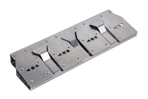
Bending sheet metal gives engineers the ability to create different shapes and designs in the material. In some cases, it can also create a whole part from a single piece of metal, which can be far more efficient than joining pieces together with hardware or welding, while creating a stronger and more durable result.
This Komaspec guide provides you with an overview of the main sheet metal bending processes, the advantages and disadvantages of each, basic design considerations, and advice for selecting materials. This guide, along with our other articles exploring the subject, will provide you with a thorough understanding of how sheet metal parts are made so you’re better equipped to discuss your products with manufacturers.
Types of Sheet Metal Bending
There are two basic methods for bending sheet metal:
- Brake press bending
- Rolling
There are also other techniques that can be employed when bends can’t be achieved through these simple means, but they are far less common.
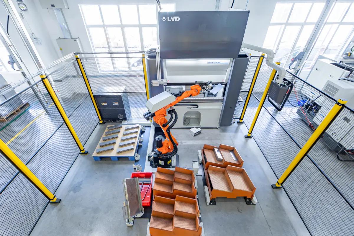
Brake Press
The brake press is the traditional option and has been a fixture of fabrication shops through much of the history of industrial manufacturing.
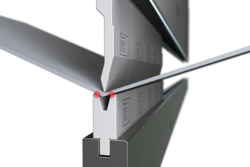
In its simplest form, this equipment presses the material between two dies to create the desired bend (as seen in the image below).
Brake presses can be used for a very wide range of sheet and plate materials. Thanks to the flexibility of the tooling and the use of high-powered hydraulics, it can accommodate material thicknesses from 0.5mm up to 20mm.
Brake presses are specified by two general parameters: tonnage and width.
The capacity of the press (or its tonnage) is the maximum amount of force it can exert. The type of material, its thickness, and the desired bend radius dictate how many tons of force are needed when fabricating a part.
Width refers to the maximum bend length the press can achieve.
Taken together, a typical brake press, for example, could be 100T x 3m.
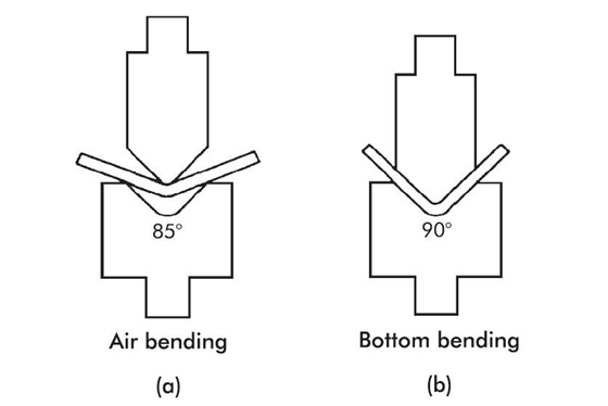
Now, there are actually two subtypes of brake press bending that we need to discuss: air bending and bottom bending.
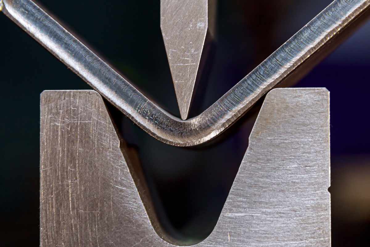
Air Bending
Air bending is the most common press brake method. It involves using a punching tool to press the material against a V-shaped bottom die. To create a bend, the press pushes the tool downwards a set distance, bending the material into the bottom die, but not completely flush against it.
This method gets its name from the gap that is left between the part being bent and the die it is pressed against (since the partial bend still allows air to flow through when the metal is pressed).
Bottom Bending
Bottom bending uses the same equipment as air bending. But instead of leaving gaps, the punch tool presses the material flat against the bottom of the die.
Bottom bending creates more accurate angles with less springback compared to air bending. However, each bend radius will require a different bottom die, use more machine pressure, and take longer to execute.
For a full breakdown of both methods, check out our guide here: Bottom Bending Vs Air Bending.
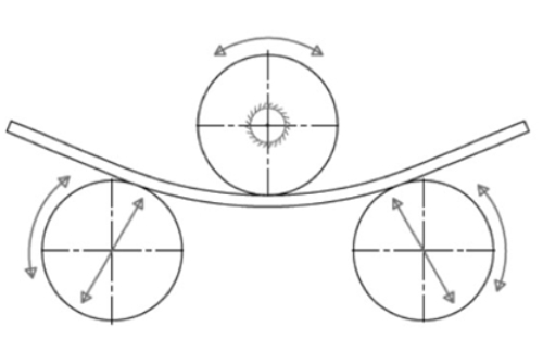
Rolling
Rolling is the process of creating a curve in sheet metal or plate by passing the material through a roller.
Rollers range in size from around 1 to 5+ meters wide, and can be used to bend materials from 1mm to 50mm+ in thickness.
The most common rolling machines have three rolls (arranged as seen below in Figure 4). The middle roll at the top is moved closer to the bottom rolls (or vice versa in some cases) and the material is then moved through the rollers as they spin, obtaining a curved shape.
As with all bending processes, some springback will occur with rolling. Sheet metal parts are generally rolled to a slightly tighter radius than required to compensate for this.
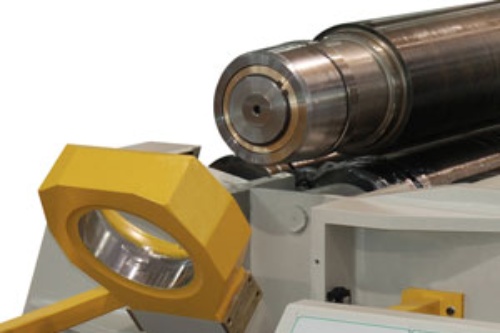
Once the rolling is complete, the bottom roller can be adjusted downwards to release the sheet metal. Most rolling machines also allow operators to open the top end yoke (as seen in figure).
When using rolling to produce a cylinder, a pre-bend operation may be required to ensure that each end of the cylinder meets after the rolling is complete.
When to Use Sheet Metal Bending in Fabrication
Bending processes can be used to create sheet metal parts and assemblies in every industry, including automotive, transport, domestic appliances, furniture, and industrial equipment.
A wide range of metal types can be bent, including common metals like steel and aluminum, as well as less common ones like copper and titanium.
Thick materials can also be bent. While “sheet metal” typically refers to materials that are under 3mm in thickness, the bending methods discussed above can be used on materials as thick as 20mm.
Thanks to the advent of modern CNC machines that can do both cutting and bending, complete parts can now be produced from a single piece of sheet metal. Being able to produce whole parts from one piece of sheet metal can cut costs and production times.
Unlike many other fabrication processes, sheet metal bending can often be combined with other value-adding operations without difficulty. For examples, metal fasteners like bolts or rivets can be used to join bent parts to others components. Other processes, such as threading, chamfering, countersinking or boring, can also be used to increase the flexibility and versatility of sheet metal components.
Check out our article on “Value Added Operations for Sheet Metal Components” for more information.
Advantages of Sheet Metal Bending
Speed of Manufacture
Since less tooling is required, bending can produce sheet metal parts very quickly. This is especially the case with automated equipment, which can run 24/7 with only a handful of personnel to monitor production.
Accuracy
With careful planning during the design stage, sheet metal parts can be manufactured to a high level of accuracy. Advancements in fabrication techniques and equipment have made it possible to achieve accuracy levels of ±0.05 mm in some cases. Not only is bending accurate to begin with, but that accuracy can be repeated consistently throughout a production run, particularly when using CNC bending machines.
Reduced Post-Processing
Other fabrication processes require post-processing before a part is complete. Heat used in welding, for example, can cause dimensional distortion in a sheet metal part, requiring straightening before it can be used. Weld splatter might also need to be removed, which is a time-consuming and labor-intensive task. With bending, the parts are ready to go as soon as they’ve gone through the equipment.
Less Weight
Bending can often create parts that have sufficient stiffness and strength, without needing additional materials to achieve these results. This reduces part weight, can be beneficial to in-use part performance, and minimize issues with transporting parts after production.
Low Cost and Little-to-No Tooling
CNC bending can significantly cut down the manual labor required to produce sheet metal parts. It also allows the work to be performed by unskilled workers rather than more expensive specialists.
Because most manufacturers already have common tools (such as punches and dies) that can produce most standard bends, using these processes can eliminate the need for specialized tooling. This means lower costs and significantly shorter lead times, as there is no need to wait for complex tooling to be produced, tested or adjusted.
Reduction in Part Complexity
With bending, it’s often possible to create relatively complex components from a single piece of material rather than using multiple parts with joints. This reduces time, minimizes the potential for errors, eliminates some failure points, and simplifies procurement.
Disadvantages of Sheet Metal Bending
Thickness Limitations
A rule of thumb in sheet metal bending is that thicker materials have a higher bend radiuse. As a result, tight bends are usually better performed on thinner sections of sheet metal rather than thicker ones.
This can mean that some complex parts can become limited to lightweight materials, suitable for low-load or no-load applications. Thicker materials can also bulge outward post-bend, crack if it is too rigid, or require a higher tonnage (and more expensive) press.
Need for Consistent Thickness
Because it’s optimal to produce parts from one piece of material, it’s better if the thickness of separate flanges on a part does not change. This means that it may be necessary to design a part so it has the same thickness throughout.
Cost of Manufacturing
Sheet metal bending is most competitively priced for low- to medium-volume production runs. When volume increases beyond 100s or 1,000s of units, stamping is generally considered a more cost-effective alternative, depending on part geometry and other design specifications. This is because CNC bending requires components to be processed one bend at a time, while multiple bends can be produced at the same time through progressive stamping. In those cases, even roboticized bending can’t compete with the cost of high-volume stamping.
While machine-assisted bending can reduce labor costs, they can still be fairly labor intensive in some cases. Some specialist bending projects may also require custom tooling, and while it costs significantly less than custom stamping tooling, it is still an additional expense.
Production Issues
In some cases, bending will leave indentations or scratches in the material, due to the pressure exerted through the narrow bending tool.
Fractures can also occur if hard metals are bent parallel to the direction the sheet metal has been rolled in during production.
Holes, slots, and other features located close to the bend can also become distorted during bending.
Finally, bends need to be in a position on the sheet metal that allows enough material to fit into the equipment without slipping.
Sheet Metal Bending Compared to Other Fabrication Processes
| Process | Best used for | Process Precision Level | Thickness (mm) | Custom tooling required | Minimum order quantity | Lead Time from CAD to 1st production |
|---|---|---|---|---|---|---|
| Laser cutting | Small to large parts with every geometry possible | ± 0.10mm | 0.5mm to 20.0mm | No | 1 to 10,000 units | Less than 1 hour |
| CNC sheet bending | Small to large parts with straight anglegeometry, multiple bend possible | ± 0.18mm | 0.5mm to 20.0mm | No | 1 to 10,000 units | Less than 1 hour |
| CNC Punching | Small to large parts with most geometry available, good for parts with multiple holes and embossed | ± 0.12mm | 0.5mm to 4.0mm* | No unless special form required | 1 to 10,000 units | Less than 1 hour |
| Stamping | High volume production with tight tolerances, restricted geometry | ± 0.05 to 0.10mm | 0.5mm to 4.0mm* | Yes from 250 USD to 100,000 USD+ | ≥5,000 units | 25 days to 40 days |
| Shearing | Thin material with simple geometry straight lines and low tolerances requirements | ± 0.50mm | 0.5mm to 4.0mm* | No | 1 to 10,000 units | Less than 1 hour |
Sheet Metal Bending Compared to Other Fabrication Processes (“Sheet Metal Fabrication”)
Materials Suitable for Bending
Most engineering materials are available in sheet form, and thus can be bent to some degree. There are, however, processing limitations with certain materials due to their different inherent properties.
Sheet metal is available in sizes ranging from gauge 50 (0.03mm) to gauge 1 (7.62mm). Bending with a brake press can be performed with all these thickness gauges and higher.
The thickness of materials is still widely referred to as gauges, despite many now being referred to in millimeters. One exception is aluminum, which is often still defined in all three dimensions by imperial measurements (feet and inches), with a gauge to denote its thickness.
For the best information on the materials available, refer to our standard materials page.
Each type of metal has its own unique characteristics. The following table outlines some of the factors you should consider when choosing materials.
| Material | Surface finish | Yield (MPA) | Tensile (MPA) | Hardness | GB standard | Sheet Metal | CNC | |||||
|---|---|---|---|---|---|---|---|---|---|---|---|---|
| Powder coating | E-Coating | Zinc plating | Dacromet | Anodized | Passivation | |||||||
| Cold Rolled Steel (CRS) | ||||||||||||
| SPCC | ✓ | ✓ | ✓ | ✓ | ≥210 | ≥350 | HB 65 - 80 | JIS G3141-2009 | ✓ | |||
| Hot Rolled Steel | ||||||||||||
| #20 | ✓ | ✓ | ✓ | ✓ | ≥245 | ≥410 | ≥143 | GB/20CrNiMo | ✓ | |||
| Q235 | ✓ | ✓ | ✓ | ✓ | ≥235 | 375 – 500 | HB 120 ±40 | GB/T 700-2006 | ✓ | ✓ | ||
| Q275 | ✓ | ✓ | ✓ | ✓ | ≥275 | 410 – 540 | HB 170-250 | GB/T 700-2006 | ✓ | ✓ | ||
| SAPH440 | ✓ | ✓ | ✓ | ✓ | ≥305 | ≥440 | HB 80 ±30 | Q/BQB 310-2009 | ✓ | |||
| Q355 | ✓ | ✓ | ✓ | ✓ | ≥355 | 470 – 630 | HB 170-220 | GB/T 1591 -2018 | ✓ | ✓ | ||
| Spring Steel | ||||||||||||
| 65Mn | ✓ | ✓ | ≥785 | ≥980 | HB 190 – 340 | GT/T 1222-2007 | ✓ | |||||
| Aluminum | ||||||||||||
| AL1060 | ✓ | ✓ | ≥35 | ≥75 | HB 26 ±5 | GB/T 3190-2008 | ✓ | |||||
| AL6061 T6 | ✓ | ✓ | ≥276 | ≥260 | HV 15 – 18 | GB/T 3190-2008 | ✓ | ✓ | ||||
| AL6063 T5 | ✓ | ✓ | ≥170 | ≥250 | HB 25 ±5 | GB/T 3190-2008 | ✓ | |||||
| AL5052 H32 | ✓ | ✓ | ≥70 | 210 – 260 | HV 11 ±2 | GB/T 3190-2008 | ✓ | |||||
| AL7075 T6 | ✓ | ✓ | ≥503 | ≥572 | HB 150 ±5 | GB/T3880-2017 | ✓ | ✓ | ||||
| Stainless Steel | ||||||||||||
| SS301 | ✓ | ✓ | ≥205 | ≥520 | HB 76 – 187 | GB/T 8170-2008 | ✓ | |||||
| SS304 | ✓ | ✓ | ≥205 | ≥520 | HB 76 – 187 | GB/T 24511-2009 | ✓ | ✓ | ||||
| SS316 | ✓ | ✓ | ≥205 | ≥520 | HB 76 – 187 | GB/T 24511-2009 | ✓ | ✓ | ||||
| SS316L | ✓ | ✓ | ≥177 | ≥480 | HB 179 – 488 | GB/T 20878-2007 | ✓ | ✓ | ||||
| Cold Galvanized Steel | ||||||||||||
| SGCC | ✓ | ≥200 | ≥380 | HB 50 – 65 | JIS-G3302 | ✓ | ||||||
Sheet Metal Materials (“Sheet Metal Standard Options in China”)
Mild Steel
The most commonly used material in the world, mild steel (also known as carbon steel) is available in both hot and cold rolled variants. Both offer excellent cold working performance, with high ductility.
The biggest downside to mild steel is the need for a rust-proof coating. Galvanized steel counters this issue by coming with a hard-wearing zinc coating that protects against moisture.
Aluminum
First used for aircraft production, aluminum alloys are now used in a vast range of applications. Because aluminum combines very well with other elements, it can offer a number of different properties.
The most commonly used aluminum alloys for sheet metal applications are the 1000 series alloys, particularly 1060 aluminum, which have high workability and low weight. These metals can be bent to tight radii without cracking, which can be a vital feature when manufacturing complex parts.
For general guidelines to material suitability for CNC bending, see the table below:
| MATERIAL | MALLEABILITY |
|---|---|
| 6061 Aluminum | Difficult to bend and often cracks. Cold bending will weaken the metal. Annealing improves malleability. |
| 5052 Aluminum | Very malleable and a good choice when using aluminum. Cracking is rare unless a part is reworked. |
| Annealed Alloy Steel | Varies based on the alloy. 4140 has good malleability. Annealing helps prevent cracking. |
| Brass | Zinc content is important. Higher zinc levels make it less malleable. Good for simple bends but complex parts may require heat. |
| Bronze | More difficult to bend and may require heat to avoid cracking. |
| Copper | Very malleable. |
| Cold Rolled Steel | Less malleable than hot rolled steel. |
| Hot Rolled Steel | More malleable than cold rolled steel. |
| Mild Steel | Very malleable. Heat not required. |
| Spring Steel | Malleable when annealed. Once work hardened, it requires heat to bend again. |
| Stainless Steel | Stainless steels like 304 and 430 are easier to form than 410, which can be brittle. Different grades will perform differently although stainless steel is prone to work hardening. |
| Titanium | Strong material, so best to design with a large internal bend radius. Overbending required because of springback. |
Material Properties (“How Material Properties Impact Air Bending Precision and Tolerances”)
Stainless Steel
Commonly used in the food and medical industries, stainless steel is an alloy of mild steel that contains at least 10.5% chromium. This gives the material corrosion resistance, with some grades excelling at resistance to acids, alkalis, and other chemicals.
Commonly used grades of stainless steel are 301 (for superior flexibility), 304 (for general use), and 316 (for greater strength and corrosion resistance).
Design Considerations for Sheet Metal Bending
Parts that will be subject to bending should be designed with the characteristics and limitations of the bending process in mind.
Bend Radius
When a material is formed into a bend, its outer surface is stretched and the inner surface is compressed. The result is a part with a rounded corner at the bent edge on both the inside and outside.
The bend radius is a measurement of the curvature of the inside bend edge. The potential radius will depend on the properties of the material, its condition, and the tooling geometry.
It’s good practice to ensure that all bends on a particular part are equal in radius because this greatly simplifies tooling set up, reducing cost.
Bend Length
The bend length required will usually depend on the design specifications of a sheet metal part. Bending machines, however, all have maximum widths according to their physical size and configuration. The standard sheet and press brake sizes go up to 2m, so if your parts are longer than this, it’s best to seek guidance.
Bend to Bend Distance
The size and shape of the tooling impose a physical limit on how close bends can be from one another. Bends without sufficient distance on the same side of a sheet will interfere with the tooling, while close bends on opposing sides will often be impossible to reach because of the bottom tool.
This commonly occurs when bending U-shaped sections where the upright flanges are longer than the horizontal section. In some cases, extra deep tooling can be used to avoid these problems. Supplementary processes like welding or bolting can also help you get the correct geometry.
Hole to Edge Distance
Materials stretch during bending, which causes internal stresses that are evenly distributed across the part. If a hole or slot is made too close to a bend, these stresses will be focused on that area, potentially causing deformation.
Springback
Metals tend to return slightly towards their original shape after bending, a phenomenon known as springback.
Several factors affect the amount of springback a part will exhibit:
- Materials with higher tensile strength have more springback
- A sharp bend radius usually produces less springback
- Wider die openings result in more springback
- The larger the bend radius relative to the material thickness, the greater the springback
In practice, springback generally only amounts to 1-2° of difference. This can usually be compensated for by adding a slightly greater bend so the springback causes the part to have the desired shape, which may be sufficient if a high level of accuracy isn’t required. When it is, using a newer CNC bending machine with built-in sensors to automatically compensate for material variability can ensure a more precise and consistent output.
Fabricators often use the K-factor to calculate springback and better understand how to compensate and achieve tighter tolerances when needed.
Processing Tolerances
As with any fabrication process, there are tolerances on dimensional accuracy. These often arise due to variations in sheet metal composition, thickness and processing. These variations should be considered when designing part to ensure the right bending methods and materials are used.
CNC control has reduced variation, and most tolerances can be achieved with modern press brake machines. It can, however, still be a pertinent issue, particularly when designing complex or precision parts.
Here are some rules of thumb:
• You can’t typically achieve a true 90° corner
• Corners will have a radius
• Bend angles have a standard tolerance of ± 1°
• Bend length tolerances are typically ±0.20 mm per bend (0.010”)
Consulting an experienced sheet metal fabricator can help you better understand tolerances in sheet metal bending processes.
Tonnage
As mentioned above, each press has a maximum tonnage capacity. It may be worth checking to make sure it will be able to perform the bends you need. If you’re not sure the tonnage will be sufficient, reach out to your manufacturer for advice before committing to a design.
Heat Affected Zones (HAZ)
Processes such as laser and plasma cutting create heat affected zones in metal. These can sometimes cause issues during bending, such as inconsistent shapes near holes and edges or cracking due to the increased surface hardness from cutting. If your parts will need other processes that create heat, be sure to take these issues into consideration.
For even more information, check out our sheet metal design guide.
| Sheet Bending | |||
|---|---|---|---|
| Linear | Bend Angle | ||
| Standard | High Precision | Standard | High Precision |
| ±0.1mm | ±0.05mm | ±1˚ | ±0.5˚ |
CNC Sheet Metal Bending - Process Tolerances and Techniques
Minimum Distance Guidelines for Features Relative to Bends
Summary
Sheet metal bending has distinct advantages over alternative sheet metal fabrication processes, including higher output, lower cost, and greater flexibility in design. It also removes many of the difficulties associated with welding, riveting, and other assembly techniques. With modern technology and careful consideration during the design process, bending can create sheet metal parts that are stronger, lighter, and quicker to produce than those made with traditional fabrication methods.
The sheet metal specialists at Komaspec are happy to work to review your product design and find the fabrication process that best suits your product design and application needs.
FAQ Section
What is sheet metal bending?
Bending is one of the most common sheet metal fabrication techniques. Bending utilizes specialized machinery to deform metal into an angular shape. This allows the creation of a wide variety of part geometries and is particularly versatile when performed alongside cutting. The most commonly used method for each process is brake press bending and CNC laser cutting.
What is sheet metal bending used for?
Sheet metal typically refers to materials under 3mm thick, but bending can be performed on materials far in excess of this, up to 8mm or more depending on the tonnage and material yield strength of the press being used. The process is very flexible and can accommodate a range of materials and thicknesses.
Bending is used to make a vast array of different parts that are used in every industry, including automotive, transport, domestic appliances, furniture, and industrial equipment.
What are the advantages of sheet metal bending?
Some of the major advantages of sheet metal bending include the speed of manufacture, its high accuracy levels, the reduced need for post processing, lower part weight, lower cost, the reduction or elimination of tooling, and reducing the number of parts produced during manufacture.
What are the disadvantages of sheet metal bending?
The downsides of sheet metal bending include limitations on how thick the materials can be, the need for consistent material thickness, the extra tolerance (roughly ±0.2mm per bend), and the cost of manufacturing for certain types of parts.
The specific downsides will differ from one bending method to another. CNC bending will require relief cuts to be added to the part in order to prevent material deformation or “mushrooming” due to the bending process. Stamping will have lower cost and higher precision, but require custom tooling. Rolling is typically a more manual process and can only produce limited types of bends.
What are some of the bending methods?
Sheet metal bending methods include air bending (in which the material is partially pressed into a V-shaped die), bottom bending (where the material is pressed fully against the die), and rolling (where the material is passed through cylinders to create a rounded bend).
Which materials are suitable for bending?
Most engineering materials are available in sheet form, meaning they can be bent to some extent. However, there are limitations depending on the bending process and the material’s properties. In general, the harder the material, the greater the risk for cracking or deformation.
How should a part be designed for bending?
Parts that will be made using bending equipment should be designed from the outset with the limitations and characteristics of the process in mind. You will have to consider the bend radius, hole to edge distance, bend to bend distance, springback, and processing tolerances.
| Tolerances | |
|---|---|
| Forming or bending | +/- 0.508 mm (0.020") |
| Bend to hole or feature | +/-0.254 mm (0.010") |
| Diameters with inserts | +/-0.0762 mm (0.003") |
| Angularity | +/- 1° |
| Holes | +/-0.127 mm (0.005") |
| Edge to edge | ±0.127 mm (0.005") |
| Edge to hole | ±0.127 mm (0.005") |
| Hole to hole | ±0.127 mm (0.005") |
| Hole to hardware | ±0.254 mm (0.010") |
| Edge to hardware | ±0.254 mm (0.010") |
| Hardware to hardware | ±0.381 mm (0.015") |
| Bend to hole | ±0.381 mm (0.015") |
| Bend to hardware | ±0.381 mm (0.015") |
| Bend to edge | ±0.254 mm (0.010") |
| Bend to bend | ±0.381 mm (0.015") |
Tolerances Guidelines for Sheet Metal Fabrication